Cirkit Designer Logo
Cirkit Designer
Your all-in-one circuit design IDE
Home / 
Component Documentation

How to Use IRF3205 H-Bridge: Examples, Pinouts, and Specs

Image of IRF3205 H-Bridge
Cirkit Designer LogoDesign with IRF3205 H-Bridge in Cirkit Designer

Introduction

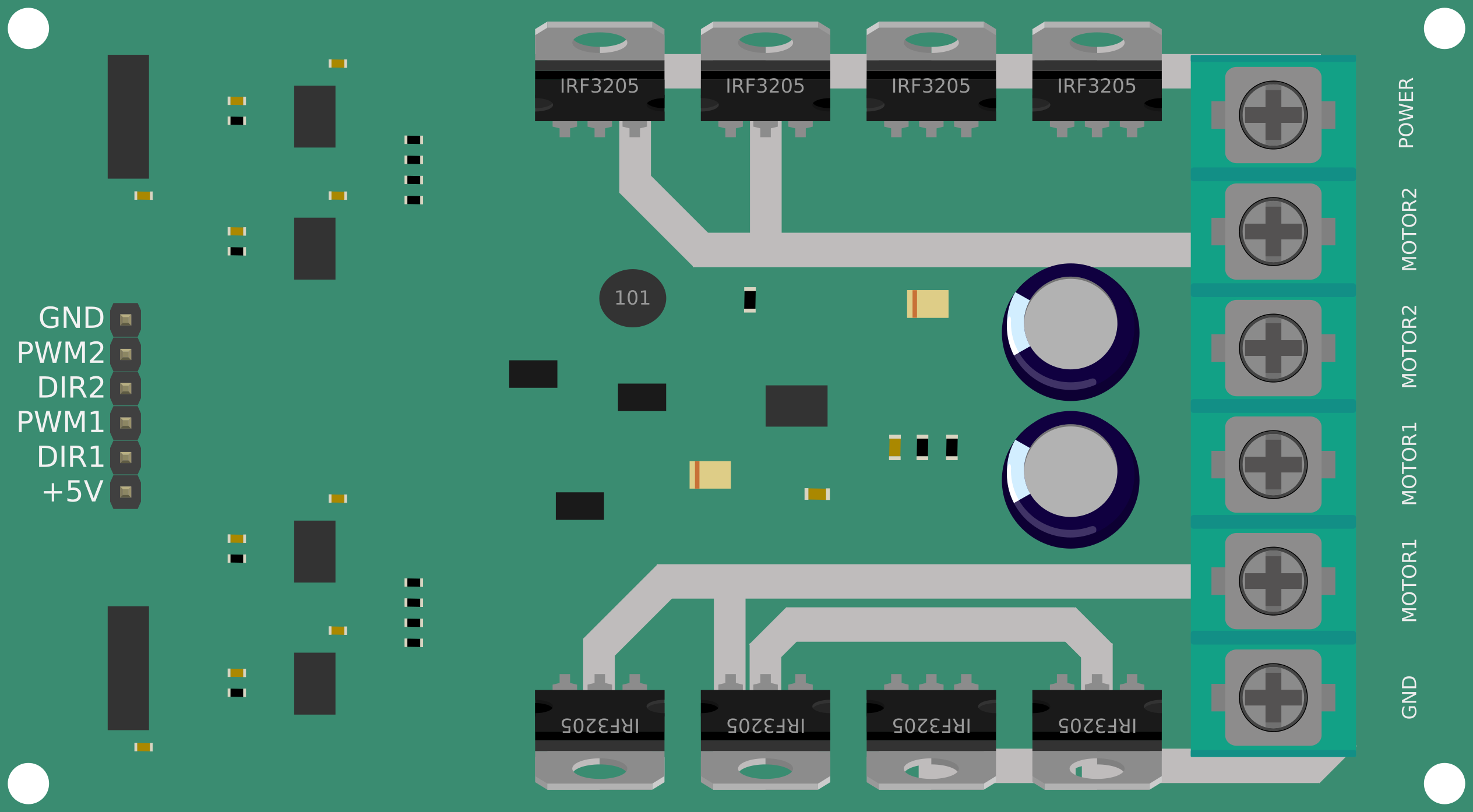
The IRF3205 is a high-speed N-channel MOSFET commonly used in H-bridge configurations for driving motors and other inductive loads. Its low on-resistance and high current handling capabilities make it ideal for efficient power conversion and control applications. The H-bridge configuration allows for bidirectional control of DC motors, making it a popular choice in robotics, motor drivers, and power management systems.

Explore Projects Built with IRF3205 H-Bridge

Use Cirkit Designer to design, explore, and prototype these projects online. Some projects support real-time simulation. Click "Open Project" to start designing instantly!
Arduino-Controlled Line Following Robot with H-Bridge Motor Driver and IR Sensors
Image of seguidor de linea: A project utilizing IRF3205 H-Bridge in a practical application
This circuit is designed to control two DC motors using an H-bridge (ponte h) connected to an Arduino UNO microcontroller. The Arduino receives input from two TCRT 5000 IR sensors to determine the path and controls the motors to move forward, backward, or turn left/right based on the sensor readings. The motors are powered by a 2x 18650 battery pack, and the entire system is intended for applications such as line following robots or automated guided vehicles.
Cirkit Designer LogoOpen Project in Cirkit Designer
ESP32-Controlled Multi-Axis Actuator System with Orientation Sensing and Light Detection
Image of Auto_Level_Table: A project utilizing IRF3205 H-Bridge in a practical application
This circuit features an ESP32 S3 N32R8V microcontroller interfaced with multiple IBT-2 H-Bridge Motor Drivers to control several Linear Actuators, and it receives input from KY-018 LDR Photo Resistors and Pushbuttons. The ESP32 is powered by a 5V supply from an Adafruit MPM3610 5V Buck Converter, while the Linear Actuators and Motor Drivers are powered by a 12V 7Ah battery. Additionally, the ESP32 communicates with an Adafruit BNO085 9-DOF Orientation IMU Fusion Breakout for orientation sensing.
Cirkit Designer LogoOpen Project in Cirkit Designer
Arduino Mega 2560 Controlled Multi-Motor Robot with RC Receiver and H-Bridge Drivers
Image of battle bot: A project utilizing IRF3205 H-Bridge in a practical application
This circuit is designed to control multiple DC motors using an Arduino Mega 2560 microcontroller and IBT-2 H-Bridge Motor Drivers. The Arduino receives input signals from an RC receiver and drives the motors at variable speeds, including forward and backward directions, as well as stopping them. The system is powered by a 12V battery, and the microcontroller's code provides functions for motor speed calibration, reading transmitter signals, and testing individual motor movements.
Cirkit Designer LogoOpen Project in Cirkit Designer
Arduino UNO Controlled Dual DC Motor Robot with IR Remote
Image of Copy of rob: A project utilizing IRF3205 H-Bridge in a practical application
This circuit is a motor control system using an Arduino UNO to drive two DC motors via an H-bridge module. The Arduino receives IR signals to control the speed and direction of the motors, powered by a 2x 18650 battery pack.
Cirkit Designer LogoOpen Project in Cirkit Designer

Explore Projects Built with IRF3205 H-Bridge

Use Cirkit Designer to design, explore, and prototype these projects online. Some projects support real-time simulation. Click "Open Project" to start designing instantly!
Image of seguidor de linea: A project utilizing IRF3205 H-Bridge in a practical application
Arduino-Controlled Line Following Robot with H-Bridge Motor Driver and IR Sensors
This circuit is designed to control two DC motors using an H-bridge (ponte h) connected to an Arduino UNO microcontroller. The Arduino receives input from two TCRT 5000 IR sensors to determine the path and controls the motors to move forward, backward, or turn left/right based on the sensor readings. The motors are powered by a 2x 18650 battery pack, and the entire system is intended for applications such as line following robots or automated guided vehicles.
Cirkit Designer LogoOpen Project in Cirkit Designer
Image of Auto_Level_Table: A project utilizing IRF3205 H-Bridge in a practical application
ESP32-Controlled Multi-Axis Actuator System with Orientation Sensing and Light Detection
This circuit features an ESP32 S3 N32R8V microcontroller interfaced with multiple IBT-2 H-Bridge Motor Drivers to control several Linear Actuators, and it receives input from KY-018 LDR Photo Resistors and Pushbuttons. The ESP32 is powered by a 5V supply from an Adafruit MPM3610 5V Buck Converter, while the Linear Actuators and Motor Drivers are powered by a 12V 7Ah battery. Additionally, the ESP32 communicates with an Adafruit BNO085 9-DOF Orientation IMU Fusion Breakout for orientation sensing.
Cirkit Designer LogoOpen Project in Cirkit Designer
Image of battle bot: A project utilizing IRF3205 H-Bridge in a practical application
Arduino Mega 2560 Controlled Multi-Motor Robot with RC Receiver and H-Bridge Drivers
This circuit is designed to control multiple DC motors using an Arduino Mega 2560 microcontroller and IBT-2 H-Bridge Motor Drivers. The Arduino receives input signals from an RC receiver and drives the motors at variable speeds, including forward and backward directions, as well as stopping them. The system is powered by a 12V battery, and the microcontroller's code provides functions for motor speed calibration, reading transmitter signals, and testing individual motor movements.
Cirkit Designer LogoOpen Project in Cirkit Designer
Image of Copy of rob: A project utilizing IRF3205 H-Bridge in a practical application
Arduino UNO Controlled Dual DC Motor Robot with IR Remote
This circuit is a motor control system using an Arduino UNO to drive two DC motors via an H-bridge module. The Arduino receives IR signals to control the speed and direction of the motors, powered by a 2x 18650 battery pack.
Cirkit Designer LogoOpen Project in Cirkit Designer

Common Applications and Use Cases

  • DC motor control in robotics and automation
  • Power inverters and converters
  • High-current switching applications
  • Battery-powered systems
  • Stepper motor drivers

Technical Specifications

Key Technical Details

Parameter Value
MOSFET Type N-Channel
Maximum Drain-Source Voltage (VDS) 55V
Maximum Continuous Drain Current (ID) 110A
Gate Threshold Voltage (VGS(th)) 2.0V - 4.0V
Maximum Gate-Source Voltage (VGS) ±20V
RDS(on) (On-Resistance) 8 mΩ (at VGS = 10V)
Power Dissipation (PD) 200W
Operating Temperature Range -55°C to +175°C
Package Type TO-220

Pin Configuration and Descriptions

Pin Number Pin Name Description
1 Gate (G) Controls the MOSFET switching (connected to PWM)
2 Drain (D) Connected to the load (e.g., motor or resistor)
3 Source (S) Connected to ground or the negative terminal

Usage Instructions

How to Use the IRF3205 in an H-Bridge Circuit

  1. H-Bridge Configuration:
    An H-bridge consists of four MOSFETs (two IRF3205s for the low side and two P-channel or N-channel MOSFETs for the high side). This configuration allows for bidirectional control of a DC motor by alternating the current flow through the motor.

  2. Gate Drive Requirements:

    • The IRF3205 requires a gate voltage (VGS) of at least 10V for optimal performance. Use a gate driver circuit or a microcontroller with a logic-level MOSFET driver to ensure proper switching.
    • Avoid leaving the gate floating; use a pull-down resistor (e.g., 10kΩ) to prevent accidental switching.
  3. Power Supply Considerations:

    • Ensure the power supply voltage does not exceed the maximum VDS rating of 55V.
    • Use decoupling capacitors (e.g., 100µF electrolytic and 0.1µF ceramic) near the power supply to reduce noise and voltage spikes.
  4. Heat Dissipation:

    • The IRF3205 can handle high currents, but it generates heat during operation. Use a heatsink or active cooling to maintain safe operating temperatures.
  5. Sample Circuit Diagram:
    Below is a simplified H-bridge circuit using IRF3205 MOSFETs for motor control:

        +V (Power Supply)
           |
           |----+----+----+
                |    |    |
               D1   D2   Motor
                |    |    |
               GND  GND  GND
    

Arduino UNO Example Code

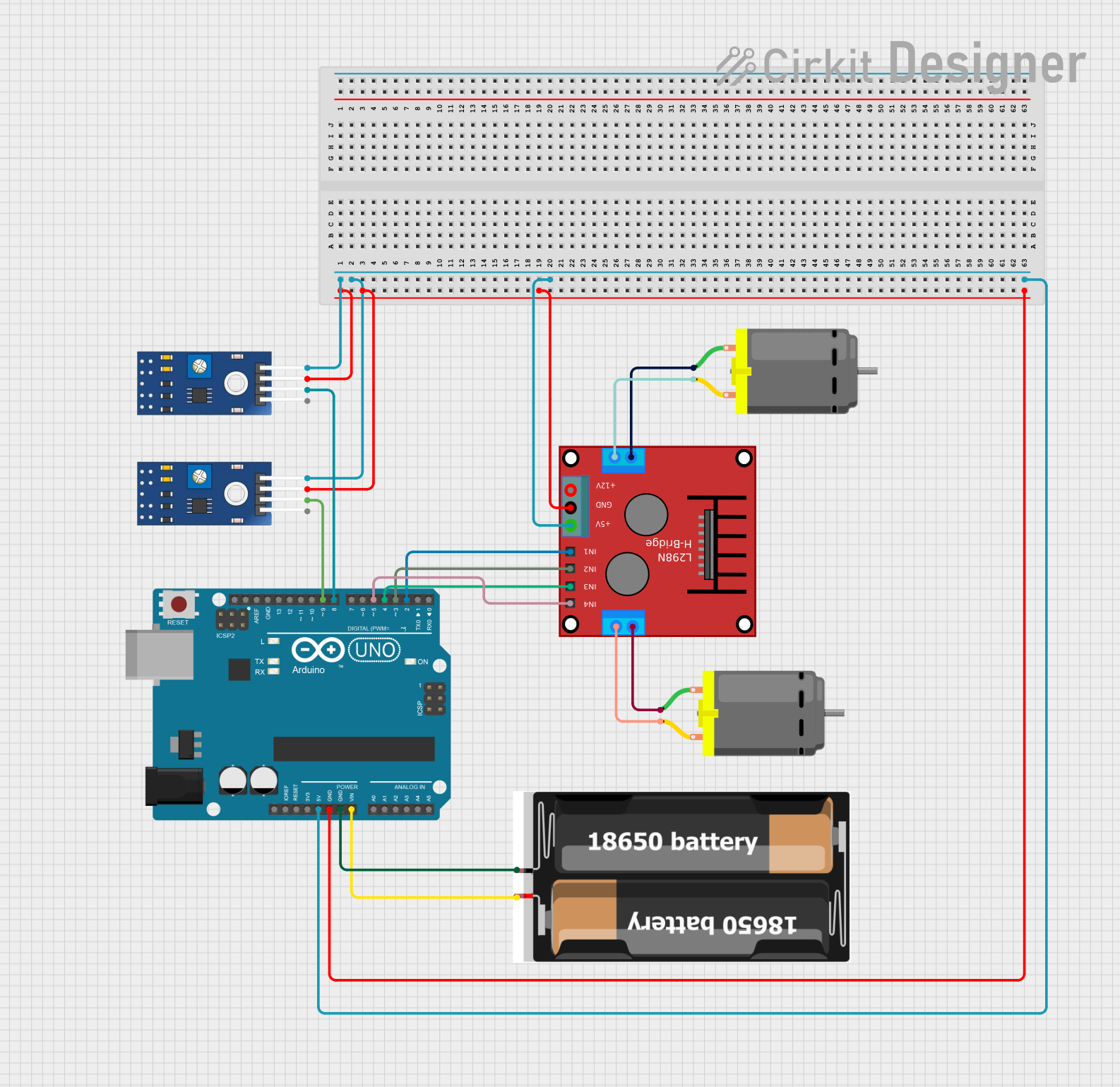
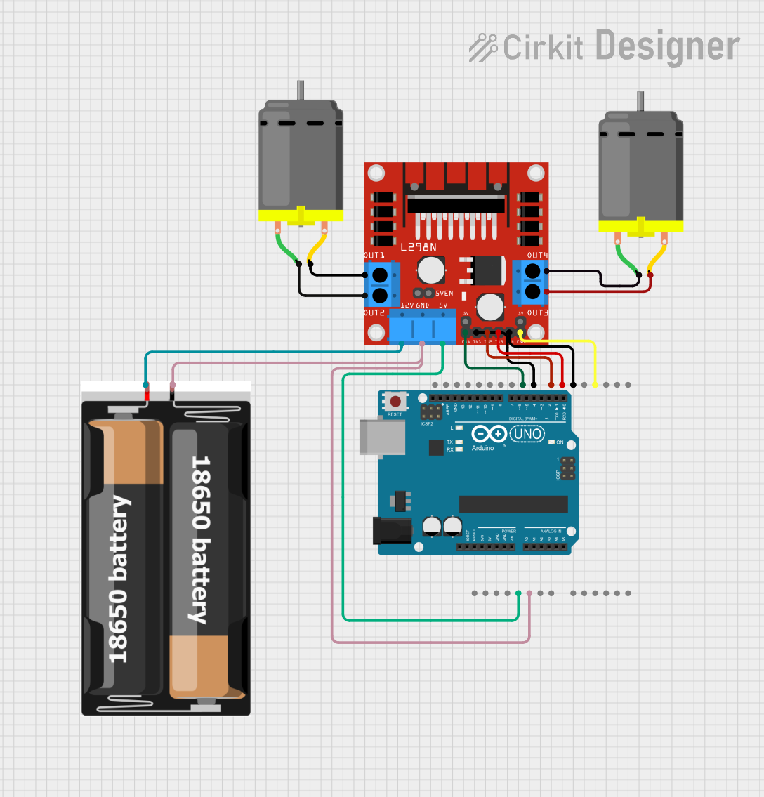
The following code demonstrates how to control a DC motor using an H-bridge with IRF3205 MOSFETs and an Arduino UNO.

// Define motor control pins
const int motorPin1 = 9; // PWM pin for one side of the H-bridge
const int motorPin2 = 10; // PWM pin for the other side of the H-bridge

void setup() {
  // Set motor pins as outputs
  pinMode(motorPin1, OUTPUT);
  pinMode(motorPin2, OUTPUT);
}

void loop() {
  // Rotate motor in one direction
  analogWrite(motorPin1, 255); // Full speed forward
  analogWrite(motorPin2, 0);   // Stop the other side
  delay(2000);                 // Run for 2 seconds

  // Rotate motor in the opposite direction
  analogWrite(motorPin1, 0);   // Stop one side
  analogWrite(motorPin2, 255); // Full speed reverse
  delay(2000);                 // Run for 2 seconds

  // Stop the motor
  analogWrite(motorPin1, 0);
  analogWrite(motorPin2, 0);
  delay(1000);                 // Pause for 1 second
}

Important Considerations and Best Practices

  • Gate Drive Voltage: Ensure the gate voltage is sufficient to fully turn on the MOSFET (10V recommended).
  • Flyback Diodes: Use flyback diodes across the motor terminals to protect the MOSFETs from voltage spikes caused by inductive loads.
  • Current Limiting: Add a current-limiting resistor or fuse to prevent damage to the MOSFETs in case of a short circuit.
  • PCB Layout: Use wide traces for high-current paths and minimize the distance between the MOSFETs and the load.

Troubleshooting and FAQs

Common Issues and Solutions

  1. MOSFET Overheating:

    • Cause: Insufficient cooling or high RDS(on).
    • Solution: Attach a heatsink or use active cooling. Ensure the gate voltage is at least 10V to minimize on-resistance.
  2. Motor Not Rotating:

    • Cause: Incorrect wiring or insufficient gate drive voltage.
    • Solution: Double-check the circuit connections and ensure the gate voltage is within the recommended range.
  3. MOSFET Not Switching:

    • Cause: Floating gate or damaged MOSFET.
    • Solution: Add a pull-down resistor to the gate and test the MOSFET with a multimeter.
  4. Voltage Spikes Damaging the MOSFET:

    • Cause: Inductive load without flyback diodes.
    • Solution: Add flyback diodes across the motor terminals to suppress voltage spikes.

FAQs

Q1: Can I use the IRF3205 directly with a 5V logic signal from a microcontroller?
A1: No, the IRF3205 requires a gate voltage of at least 10V for optimal performance. Use a logic-level MOSFET driver or a gate driver circuit.

Q2: What is the maximum motor current the IRF3205 can handle?
A2: The IRF3205 can handle up to 110A, but ensure proper cooling and consider the power dissipation limits.

Q3: Can I use the IRF3205 for high-frequency switching?
A3: Yes, the IRF3205 is suitable for high-frequency switching, but ensure the gate driver can provide sufficient current for fast switching.

Q4: Do I need to use all four IRF3205 MOSFETs in an H-bridge?
A4: Typically, two IRF3205s are used for the low side, while the high side may use P-channel MOSFETs or other N-channel MOSFETs with a bootstrap circuit.