
How to Use Raspberry Pi 4B: Examples, Pinouts, and Specs
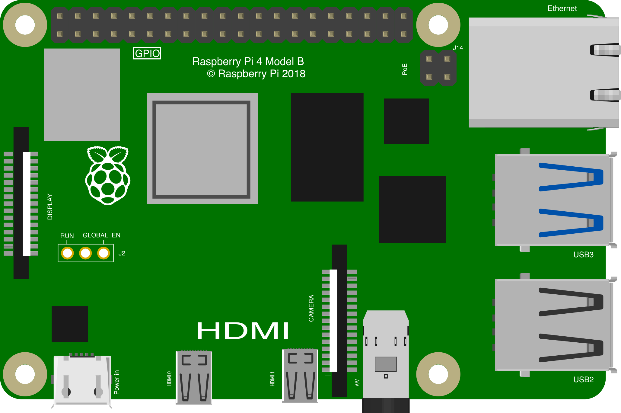
 Design with Raspberry Pi 4B in Cirkit Designer
Introduction
The Raspberry Pi 4 Model B, manufactured by Raspberry Pi Ltd, is a compact and affordable single-board computer designed for a wide range of applications. It features a powerful quad-core processor, up to 8GB of RAM, multiple USB ports, dual HDMI outputs, and built-in Wi-Fi and Bluetooth connectivity. This versatile device is ideal for projects ranging from learning programming and building IoT devices to creating media centers and running lightweight servers.
Explore Projects Built with Raspberry Pi 4B
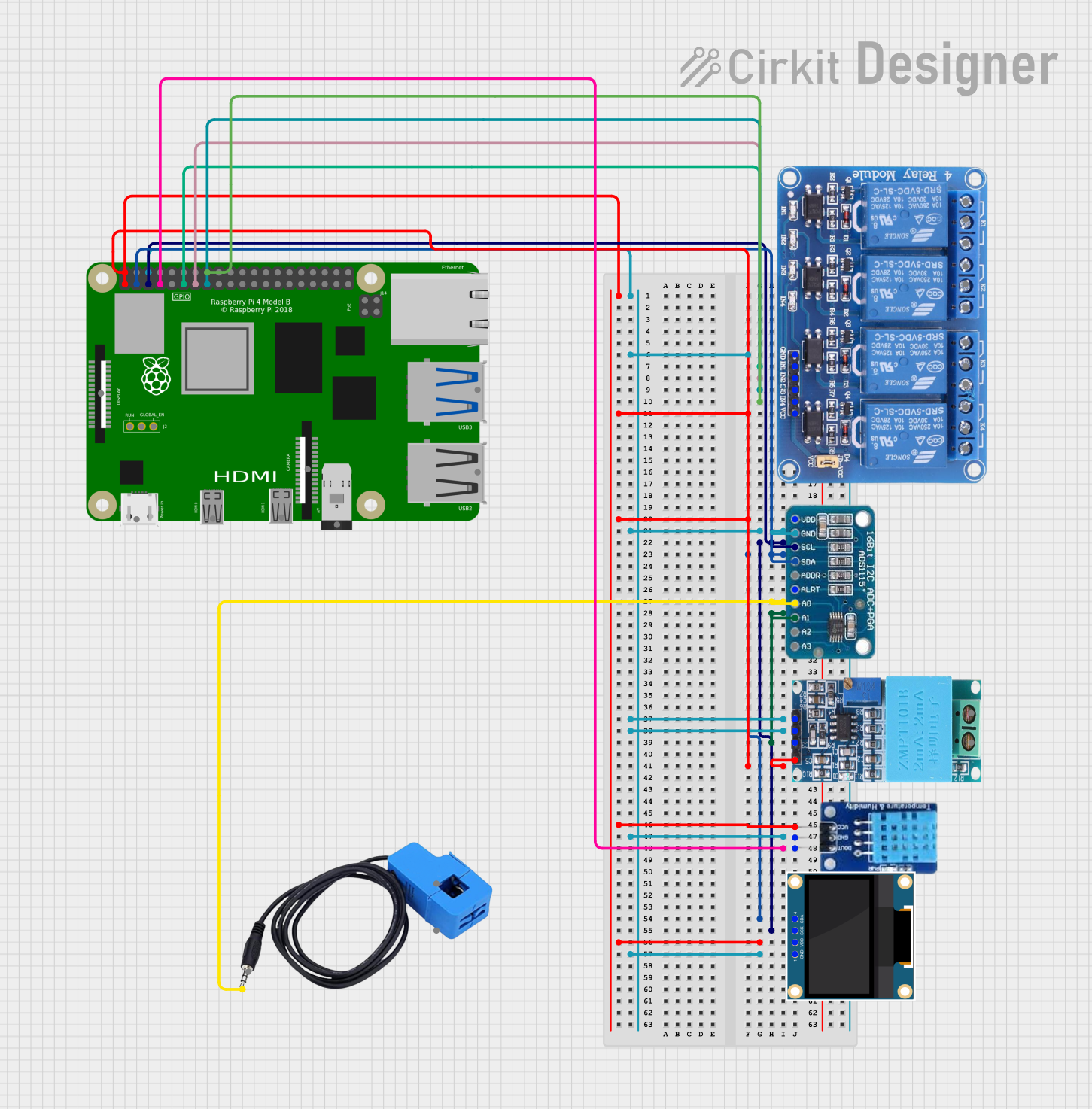 Open Project in Cirkit Designer
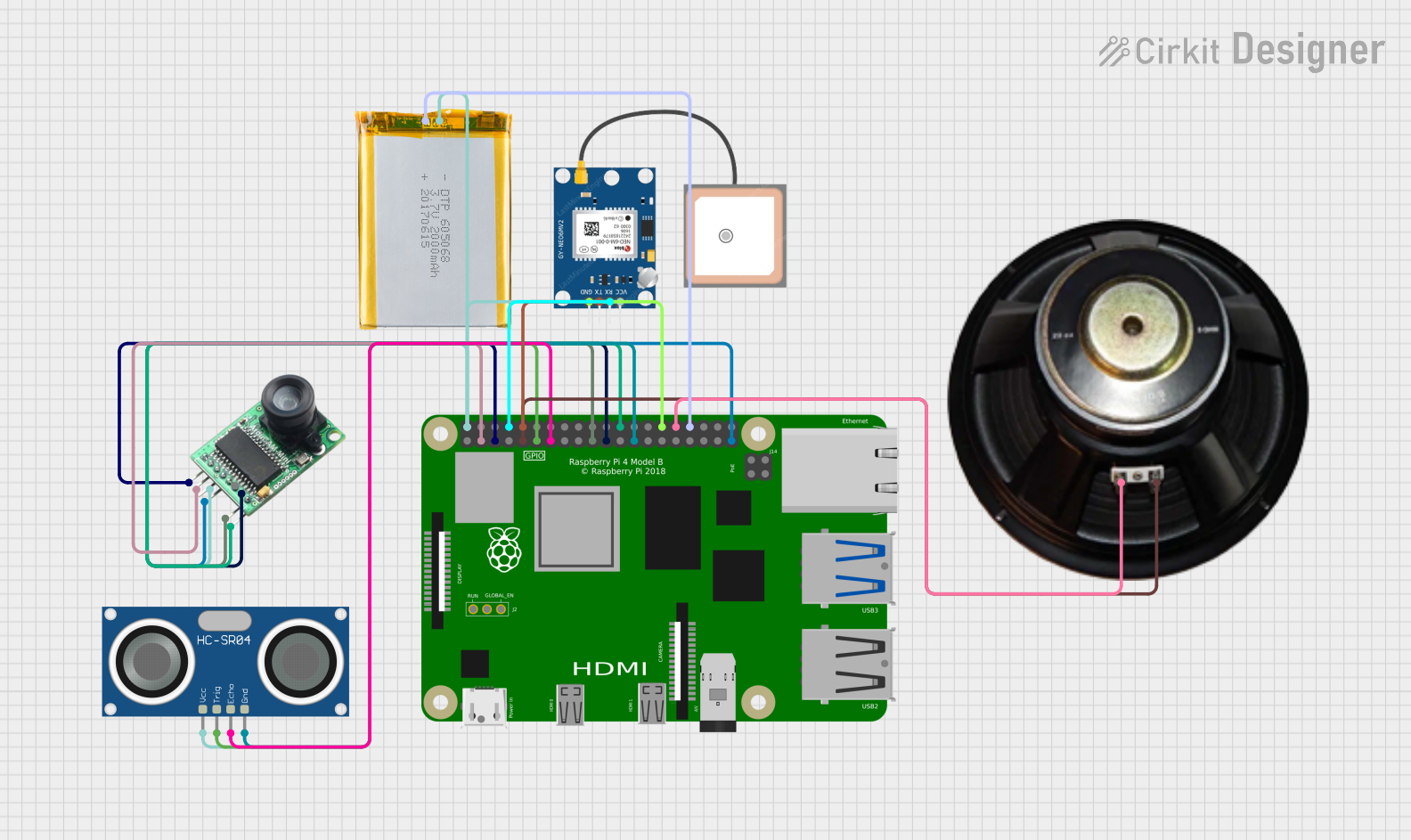 Open Project in Cirkit Designer
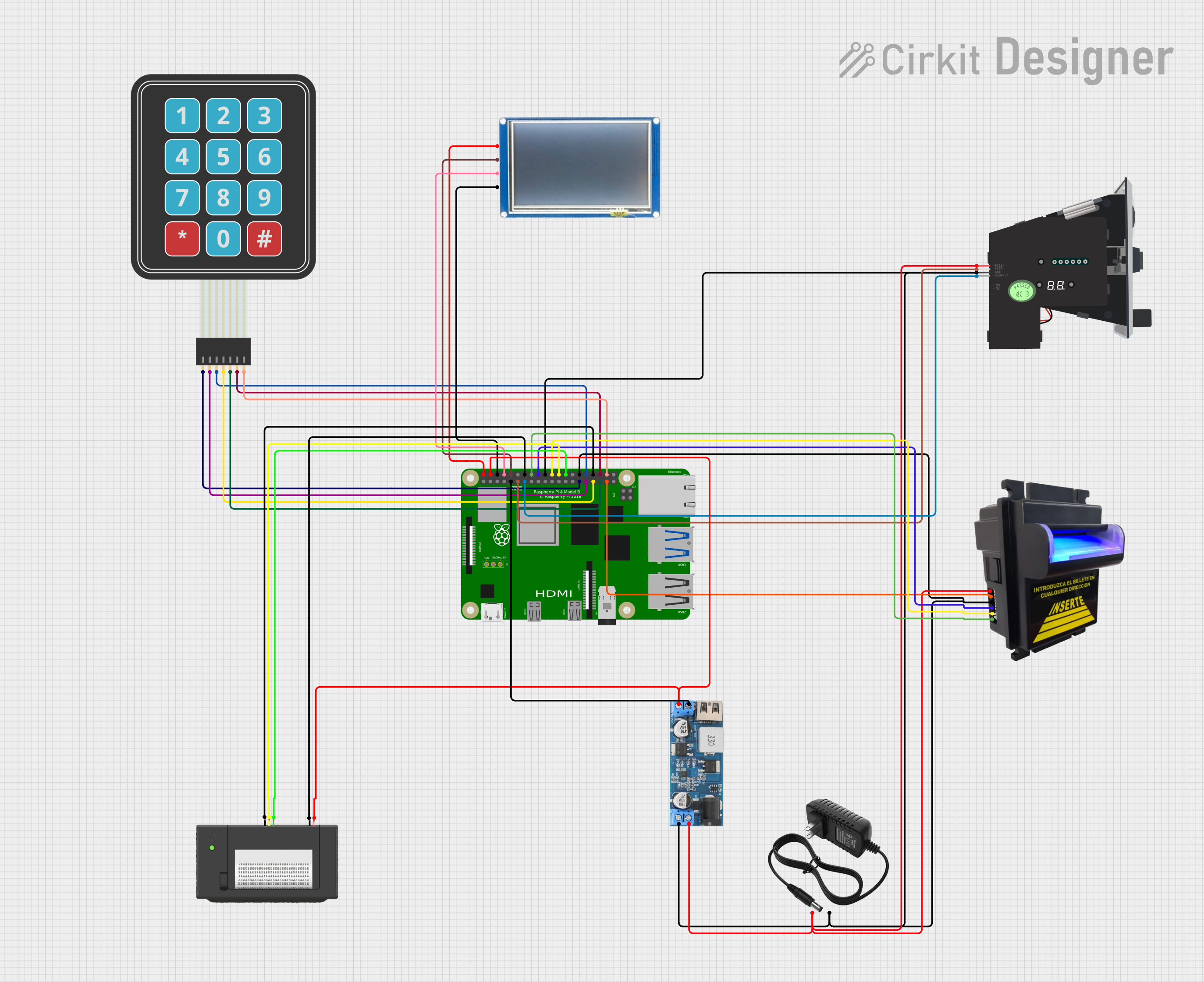 Open Project in Cirkit Designer
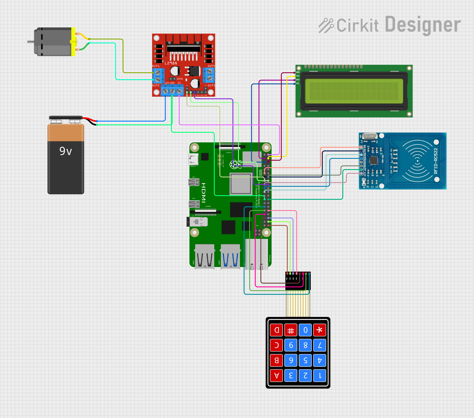 Open Project in Cirkit Designer
Explore Projects Built with Raspberry Pi 4B
Open Project in Cirkit DesignerOpen Project in Cirkit DesignerOpen Project in Cirkit DesignerOpen Project in Cirkit DesignerCommon Applications and Use Cases
- Learning and Education: Ideal for teaching programming, Linux, and electronics.
- IoT Projects: Acts as a hub for Internet of Things devices.
- Media Centers: Can be used to build a home theater system with software like Kodi.
- Home Automation: Powers smart home systems and automation projects.
- Lightweight Servers: Suitable for hosting web servers, file servers, or VPNs.
- Robotics: Serves as the brain for robotics projects.
- Retro Gaming: Runs emulators for classic gaming systems.
Technical Specifications
The Raspberry Pi 4 Model B offers a range of features and capabilities. Below are its key technical specifications:
General Specifications
| Feature | Specification |
|---|---|
| Processor | Broadcom BCM2711, Quad-core Cortex-A72 (ARM v8) 64-bit SoC @ 1.5GHz |
| RAM Options | 2GB, 4GB, or 8GB LPDDR4-3200 SDRAM |
| GPU | VideoCore VI, supporting OpenGL ES 3.0 |
| Storage | MicroSD card slot for OS and data storage |
| Connectivity | 2.4GHz and 5.0GHz IEEE 802.11b/g/n/ac Wi-Fi, Bluetooth 5.0, BLE |
| Ethernet | Gigabit Ethernet |
| USB Ports | 2 × USB 3.0, 2 × USB 2.0 |
| Video Output | 2 × micro-HDMI ports (up to 4Kp60 supported) |
| Audio Output | 3.5mm stereo audio and composite video jack, HDMI audio |
| GPIO | 40-pin GPIO header, backward-compatible with previous Raspberry Pi models |
| Power Supply | 5V/3A via USB-C connector |
| Dimensions | 85.6mm × 56.5mm × 17mm |
Pin Configuration and Descriptions
The Raspberry Pi 4B features a 40-pin GPIO header for interfacing with external devices. Below is the pinout:
| Pin Number | Pin Name | Description |
|---|---|---|
| 1 | 3.3V Power | 3.3V power supply |
| 2 | 5V Power | 5V power supply |
| 3 | GPIO2 (SDA1) | I2C Data |
| 4 | 5V Power | 5V power supply |
| 5 | GPIO3 (SCL1) | I2C Clock |
| 6 | Ground | Ground |
| 7 | GPIO4 | General-purpose I/O |
| 8 | GPIO14 (TXD0) | UART Transmit |
| 9 | Ground | Ground |
| 10 | GPIO15 (RXD0) | UART Receive |
| ... | ... | ... (Refer to official documentation for full pinout) |
Usage Instructions
How to Use the Raspberry Pi 4B in a Circuit
- Powering the Raspberry Pi: Use a 5V/3A USB-C power supply to power the board. Ensure the power supply is reliable to avoid voltage drops.
- Connecting Peripherals: Attach a monitor via the micro-HDMI ports, a keyboard and mouse via USB ports, and a microSD card with the operating system installed.
- Booting the Device: Insert the microSD card, connect the power supply, and the Raspberry Pi will boot automatically.
- Using GPIO Pins: Connect external devices like LEDs, sensors, or motors to the GPIO pins. Use appropriate resistors and circuits to avoid damaging the board.
Important Considerations and Best Practices
- Cooling: The Raspberry Pi 4B can get hot under heavy loads. Use a heatsink or fan for better thermal management.
- Static Electricity: Handle the board carefully to avoid static discharge, which can damage components.
- OS Installation: Use the official Raspberry Pi Imager tool to install an operating system like Raspberry Pi OS on the microSD card.
- Power Supply: Always use a high-quality power supply to ensure stable operation.
Example: Blinking an LED with GPIO and Arduino Code
The Raspberry Pi 4B can control an LED using its GPIO pins. Below is an example Python script for blinking an LED connected to GPIO pin 17:
Import the necessary library for GPIO control
import RPi.GPIO as GPIO import time
Set up GPIO mode and pin
GPIO.setmode(GPIO.BCM) # Use Broadcom pin numbering GPIO.setup(17, GPIO.OUT) # Set GPIO pin 17 as an output
try: while True: GPIO.output(17, GPIO.HIGH) # Turn LED on time.sleep(1) # Wait for 1 second GPIO.output(17, GPIO.LOW) # Turn LED off time.sleep(1) # Wait for 1 second except KeyboardInterrupt: # Clean up GPIO settings on exit GPIO.cleanup()
Connecting to Arduino UNO
The Raspberry Pi 4B can communicate with an Arduino UNO via UART, I2C, or SPI. For example, to send data via UART:
- Connect the Raspberry Pi's GPIO14 (TXD) to the Arduino's RX pin.
- Connect the Raspberry Pi's GPIO15 (RXD) to the Arduino's TX pin.
- Use a level shifter if necessary to match voltage levels.
Troubleshooting and FAQs
Common Issues and Solutions
The Raspberry Pi does not boot:
- Ensure the microSD card is properly inserted and contains a valid OS image.
- Check the power supply for sufficient voltage and current.
- Verify that the HDMI cable is securely connected to the monitor.
Overheating:
- Use a heatsink or fan to improve cooling.
- Avoid running the Raspberry Pi in enclosed spaces without ventilation.
Wi-Fi or Bluetooth not working:
- Ensure the Raspberry Pi is within range of the Wi-Fi router.
- Update the operating system to the latest version to fix potential driver issues.
GPIO pins not working:
- Double-check the pin connections and ensure the correct pin numbering is used in the code.
- Verify that the GPIO pins are not damaged or shorted.
FAQs
Can I power the Raspberry Pi 4B via GPIO pins? Yes, you can power the Raspberry Pi using the 5V and GND pins on the GPIO header, but this bypasses the onboard power management and is not recommended.
What operating systems are supported? The Raspberry Pi 4B supports Raspberry Pi OS, Ubuntu, and other Linux-based distributions. It can also run lightweight versions of Windows 10 IoT Core.
Can I connect multiple displays? Yes, the Raspberry Pi 4B supports dual monitors via its two micro-HDMI ports, with resolutions up to 4K.
How do I reset the Raspberry Pi? Disconnect and reconnect the power supply to perform a hard reset.