Cirkit Designer Logo
Cirkit Designer
Your all-in-one circuit design IDE
Home / 
Component Documentation

How to Use 20x80mm perf board: Examples, Pinouts, and Specs

Image of 20x80mm perf board
Cirkit Designer LogoDesign with 20x80mm perf board in Cirkit Designer

Introduction

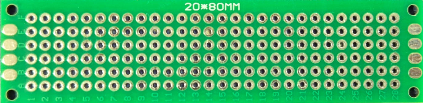
The 20x80mm perf board is a compact, perforated board designed for prototyping electronic circuits. It features a grid of evenly spaced holes that allow users to mount components and create custom circuit layouts. This versatile tool is ideal for hobbyists, students, and professionals who need a reliable platform for testing and building electronic designs.

Explore Projects Built with 20x80mm perf board

Use Cirkit Designer to design, explore, and prototype these projects online. Some projects support real-time simulation. Click "Open Project" to start designing instantly!
Raspberry Pi 4B-Based Multi-Sensor Interface Hub with GPS and GSM
Image of Rocket: A project utilizing 20x80mm perf board in a practical application
This circuit features a Raspberry Pi 4B interfaced with an IMX296 color global shutter camera, a Neo 6M GPS module, an Adafruit BMP388 barometric pressure sensor, an MPU-6050 accelerometer/gyroscope, and a Sim800l GSM module for cellular connectivity. Power management is handled by an MT3608 boost converter, which steps up the voltage from a Lipo battery, with a resettable fuse PTC and a 1N4007 diode for protection. The Adafruit Perma-Proto HAT is used for organizing connections and interfacing the sensors and modules with the Raspberry Pi via I2C and GPIO pins.
Cirkit Designer LogoOpen Project in Cirkit Designer
Battery-Powered Sumo Robot with IR Sensors and DC Motors
Image of MASSIVE SUMO AUTO BOARD: A project utilizing 20x80mm perf board in a practical application
This circuit is designed for a robotic system, featuring a Massive Sumo Board as the central controller. It integrates multiple FS-80NK diffuse IR sensors and IR line sensors for obstacle detection and line following, respectively, and controls two GM25 DC motors via MD13s motor drivers for movement. Power is supplied by an 11.1V LiPo battery.
Cirkit Designer LogoOpen Project in Cirkit Designer
Interactive Touch and Motion Sensor System with Bela Board and OLED Display
Image of GIZMO Teaset: A project utilizing 20x80mm perf board in a practical application
This circuit integrates a Bela Board with various sensors and actuators, including a TRILL CRAFT touch sensor, an ADXXL335 accelerometer, a vibration motor, and a loudspeaker. The Bela Board processes input from the touch sensor and accelerometer, and controls the vibration motor and loudspeaker, while an OLED display provides visual feedback.
Cirkit Designer LogoOpen Project in Cirkit Designer
Battery-Powered Health Monitoring System with Nucleo WB55RG and OLED Display
Image of Pulsefex: A project utilizing 20x80mm perf board in a practical application
This circuit is a multi-sensor data acquisition system that uses a Nucleo WB55RG microcontroller to interface with a digital temperature sensor (TMP102), a pulse oximeter and heart-rate sensor (MAX30102), and a 0.96" OLED display via I2C. Additionally, it includes a Sim800l module for GSM communication, powered by a 3.7V LiPo battery.
Cirkit Designer LogoOpen Project in Cirkit Designer

Explore Projects Built with 20x80mm perf board

Use Cirkit Designer to design, explore, and prototype these projects online. Some projects support real-time simulation. Click "Open Project" to start designing instantly!
Image of Rocket: A project utilizing 20x80mm perf board in a practical application
Raspberry Pi 4B-Based Multi-Sensor Interface Hub with GPS and GSM
This circuit features a Raspberry Pi 4B interfaced with an IMX296 color global shutter camera, a Neo 6M GPS module, an Adafruit BMP388 barometric pressure sensor, an MPU-6050 accelerometer/gyroscope, and a Sim800l GSM module for cellular connectivity. Power management is handled by an MT3608 boost converter, which steps up the voltage from a Lipo battery, with a resettable fuse PTC and a 1N4007 diode for protection. The Adafruit Perma-Proto HAT is used for organizing connections and interfacing the sensors and modules with the Raspberry Pi via I2C and GPIO pins.
Cirkit Designer LogoOpen Project in Cirkit Designer
Image of MASSIVE SUMO AUTO BOARD: A project utilizing 20x80mm perf board in a practical application
Battery-Powered Sumo Robot with IR Sensors and DC Motors
This circuit is designed for a robotic system, featuring a Massive Sumo Board as the central controller. It integrates multiple FS-80NK diffuse IR sensors and IR line sensors for obstacle detection and line following, respectively, and controls two GM25 DC motors via MD13s motor drivers for movement. Power is supplied by an 11.1V LiPo battery.
Cirkit Designer LogoOpen Project in Cirkit Designer
Image of GIZMO Teaset: A project utilizing 20x80mm perf board in a practical application
Interactive Touch and Motion Sensor System with Bela Board and OLED Display
This circuit integrates a Bela Board with various sensors and actuators, including a TRILL CRAFT touch sensor, an ADXXL335 accelerometer, a vibration motor, and a loudspeaker. The Bela Board processes input from the touch sensor and accelerometer, and controls the vibration motor and loudspeaker, while an OLED display provides visual feedback.
Cirkit Designer LogoOpen Project in Cirkit Designer
Image of Pulsefex: A project utilizing 20x80mm perf board in a practical application
Battery-Powered Health Monitoring System with Nucleo WB55RG and OLED Display
This circuit is a multi-sensor data acquisition system that uses a Nucleo WB55RG microcontroller to interface with a digital temperature sensor (TMP102), a pulse oximeter and heart-rate sensor (MAX30102), and a 0.96" OLED display via I2C. Additionally, it includes a Sim800l module for GSM communication, powered by a 3.7V LiPo battery.
Cirkit Designer LogoOpen Project in Cirkit Designer

Common Applications and Use Cases

  • Prototyping and testing small electronic circuits
  • Building custom circuit boards for DIY projects
  • Educational purposes for learning circuit design
  • Repairing or modifying existing circuits
  • Creating compact, permanent circuit solutions

Technical Specifications

The 20x80mm perf board is designed to provide a durable and flexible platform for circuit prototyping. Below are its key specifications:

Specification Details
Dimensions 20mm x 80mm
Material FR4 (fiberglass-reinforced epoxy)
Hole Grid 2.54mm (0.1 inch) pitch
Hole Diameter ~1.0mm
Thickness ~1.6mm
Copper Layer Single-sided or double-sided (varies)
Weight ~5g

Pin Configuration and Descriptions

The perf board does not have predefined pins but features a grid of holes for mounting components. Below is a description of its layout:

Feature Description
Holes Arranged in a 2.54mm pitch grid for mounting through-hole components.
Copper Pads May be present around holes (depending on the type) to facilitate soldering.
Edges Smooth edges for safe handling and easy mounting in enclosures.

Usage Instructions

How to Use the 20x80mm Perf Board in a Circuit

  1. Plan Your Circuit Layout: Sketch the circuit design on paper or use software to map out the placement of components.
  2. Insert Components: Place through-hole components (e.g., resistors, capacitors, ICs) into the holes of the perf board.
  3. Solder Connections: Use a soldering iron to secure the components to the board. Ensure proper solder joints for reliable connections.
  4. Wire Connections: Use jumper wires or soldered connections to link components as per your circuit design.
  5. Test the Circuit: Verify the functionality of your circuit using a multimeter or by powering it up.

Important Considerations and Best Practices

  • Component Placement: Leave enough space between components to avoid short circuits and make soldering easier.
  • Heat Management: Avoid overheating the board while soldering to prevent damage to the copper pads or the board itself.
  • Insulation: Use heat-shrink tubing or electrical tape to insulate exposed wires and prevent accidental shorts.
  • Cutting the Board: If needed, the board can be cut to a smaller size using a hacksaw or rotary tool. Sand the edges for a smooth finish.
  • Arduino Compatibility: The 20x80mm perf board can be used to create custom shields or circuits for Arduino UNO and other microcontrollers.

Example: Connecting an LED to an Arduino UNO

Below is an example of how to use the perf board to connect an LED to an Arduino UNO:

  1. Place the LED and a 220-ohm resistor on the perf board.
  2. Solder the anode of the LED to one end of the resistor.
  3. Connect the other end of the resistor to a jumper wire leading to Arduino pin 13.
  4. Solder the cathode of the LED to a wire leading to the Arduino GND pin.
// Arduino code to blink an LED connected to pin 13
void setup() {
  pinMode(13, OUTPUT); // Set pin 13 as an output
}

void loop() {
  digitalWrite(13, HIGH); // Turn the LED on
  delay(1000);            // Wait for 1 second
  digitalWrite(13, LOW);  // Turn the LED off
  delay(1000);            // Wait for 1 second
}

Troubleshooting and FAQs

Common Issues Users Might Face

  1. Loose Connections: Components may not be securely soldered, leading to intermittent connections.
    • Solution: Re-solder the joints, ensuring a clean and solid connection.
  2. Short Circuits: Solder bridges between adjacent pads can cause short circuits.
    • Solution: Use a soldering iron and desoldering wick to remove excess solder.
  3. Overheating the Board: Excessive heat during soldering can damage the board or lift copper pads.
    • Solution: Use a temperature-controlled soldering iron and work quickly.
  4. Incorrect Layout: Misplaced components or incorrect wiring can lead to non-functional circuits.
    • Solution: Double-check the circuit design and verify connections with a multimeter.

FAQs

Q: Can I reuse a perf board after soldering?
A: Yes, but it can be challenging to remove soldered components without damaging the board. Use a desoldering pump or wick for best results.

Q: Is the perf board suitable for high-current applications?
A: Perf boards are generally not designed for high-current circuits. Use thicker wires and ensure proper heat dissipation if needed.

Q: Can I use surface-mount components on a perf board?
A: While perf boards are designed for through-hole components, surface-mount components can be used with careful soldering and additional wiring.

Q: How do I cut the perf board to a custom size?
A: Use a hacksaw or rotary tool to cut the board. Sand the edges to remove sharp edges and debris.