How to Use Adafruit Negative RGB 2x16 LCD: Examples, Pinouts, and Specs
Introduction
The Adafruit Negative RGB 2x16 LCD is a versatile display module capable of showing text and graphics in a 2-row by 16-character format. Its negative RGB backlight allows for a wide range of color customization, making it suitable for various applications such as user interfaces, status displays, and simple animations in hobbyist projects or professional devices.
Explore Projects Built with Adafruit Negative RGB 2x16 LCD
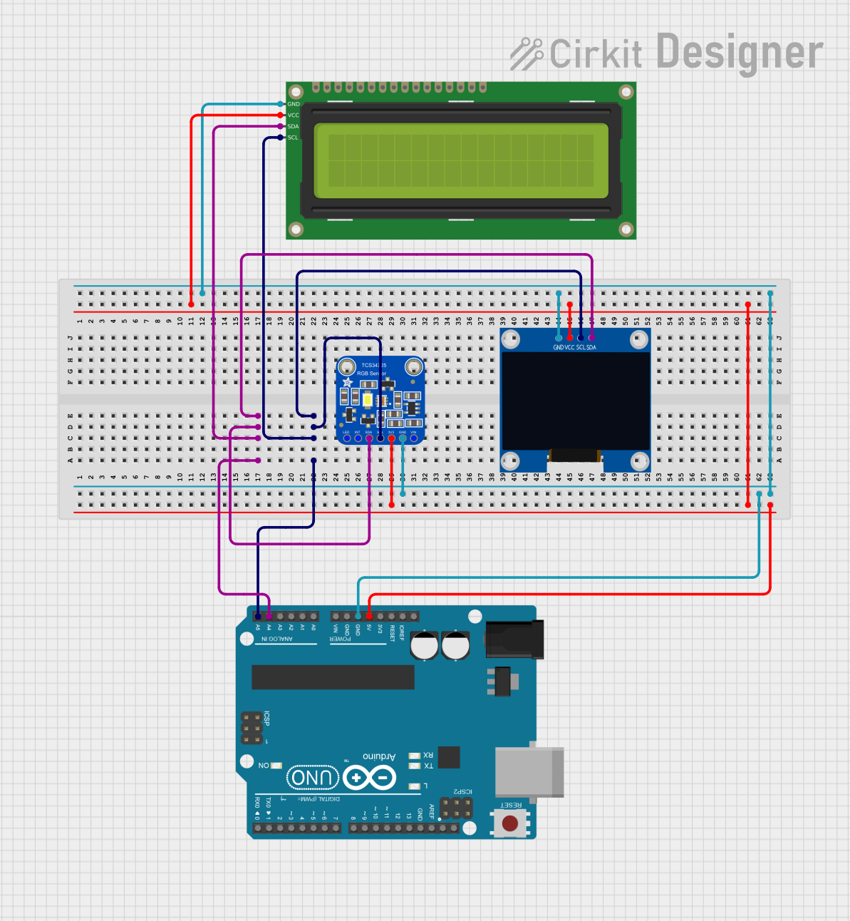


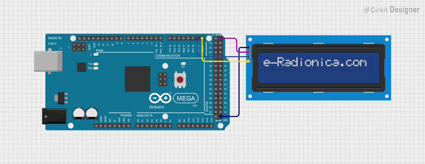
Explore Projects Built with Adafruit Negative RGB 2x16 LCD
Common Applications and Use Cases
- DIY electronics projects
- User interfaces for devices
- Status and information displays
- Prototyping for commercial products
- Educational tools for learning electronics and programming
Technical Specifications
Key Technical Details
- Display Type: Negative mode LCD
- Backlight Type: RGB LED
- Character Format: 2 rows by 16 characters
- Character Size: 5x8 pixel matrix per character
- Module Dimensions: 80mm x 36mm x 20mm
- Operating Voltage: 4.5V to 5.5V
- Logic Voltage: 3.3V or 5V compatible
- Current (with backlight): 20mA typical, up to 120mA max
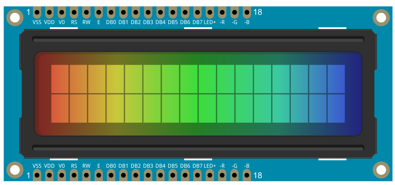
Pin Configuration and Descriptions
| Pin Number | Name | Description |
|---|---|---|
| 1 | GND | Ground connection |
| 2 | VCC | Power supply (4.5V to 5.5V) |
| 3 | VO | Contrast adjustment |
| 4 | RS | Register Select (High for data, Low for command) |
| 5 | R/W | Read/Write (High for read, Low for write) |
| 6 | E | Enable signal |
| 7-14 | D0-D7 | 8-bit data bus |
| 15 | LED+ | Anode for RGB backlight (connect to 5V through resistor) |
| 16 | LED- | Cathode for RGB backlight (connect to GND) |
Usage Instructions
How to Use the Component in a Circuit
- Power Connections: Connect pin 2 (VCC) to a 5V power supply and pin 1 (GND) to ground.
- Backlight: Connect pin 15 (LED+) to 5V through a current-limiting resistor and pin 16 (LED-) to ground.
- Data Interface: Connect pins 7-14 (D0-D7) to the microcontroller's digital pins if using 8-bit mode. For 4-bit mode, only D4-D7 are used.
- Control Pins: Connect RS, R/W, and E to digital pins on the microcontroller.
- Contrast Adjustment: Connect VO to a potentiometer for contrast control.
Important Considerations and Best Practices
- Always use a current-limiting resistor for the backlight to prevent damage.
- Adjust the contrast potentiometer to ensure characters are clearly visible.
- When using with a 3.3V logic microcontroller, ensure that the logic voltage levels are compatible.
- Avoid exposing the display to direct sunlight or high temperatures to prevent damage.
Example Code for Arduino UNO
#include <LiquidCrystal.h>

// Initialize the library with the numbers of the interface pins
LiquidCrystal lcd(12, 11, 5, 4, 3, 2);

void setup() {
  // Set up the LCD's number of columns and rows:
  lcd.begin(16, 2);
  // Print a message to the LCD.
  lcd.print("Hello, World!");
}

void loop() {
  // Set the cursor to column 0, line 1
  // (note: line 1 is the second row, since counting begins with 0):
  lcd.setCursor(0, 1);
  // Print the number of seconds since reset:
  lcd.print(millis() / 1000);
}
Troubleshooting and FAQs
Common Issues Users Might Face
- Characters not visible or very dim: Adjust the contrast potentiometer. Check the backlight current-limiting resistor and connections.
- Garbled or incorrect characters: Ensure data lines are connected properly and there are no loose connections.
- No backlight: Verify the connection and resistor for the backlight. Ensure the power supply is within the specified range.
Solutions and Tips for Troubleshooting
- Double-check wiring against the pin configuration table.
- Make sure the power supply is stable and within the recommended voltage range.
- If using with a 3.3V logic device, use a logic level converter if necessary.
FAQs
Q: Can I use this LCD with a 3.3V system? A: Yes, but ensure that the logic levels are compatible. You may need a logic level converter.
Q: How do I change the backlight color? A: The backlight color can be changed by using PWM signals on the RGB backlight pins. This is not covered in this basic documentation, but Adafruit provides guides on their website.
Q: What is the maximum current draw for the backlight? A: The maximum current draw for the backlight is 120mA. Always use a current-limiting resistor to prevent damage.
Q: Can I display graphics on this LCD? A: Yes, the LCD can display custom characters and simple graphics by defining custom character patterns.