Cirkit Designer Logo
Cirkit Designer
Your all-in-one circuit design IDE
Home / 
Component Documentation

How to Use MAIN CONTACTOR: Examples, Pinouts, and Specs

Image of MAIN CONTACTOR
Cirkit Designer LogoDesign with MAIN CONTACTOR in Cirkit Designer

Introduction

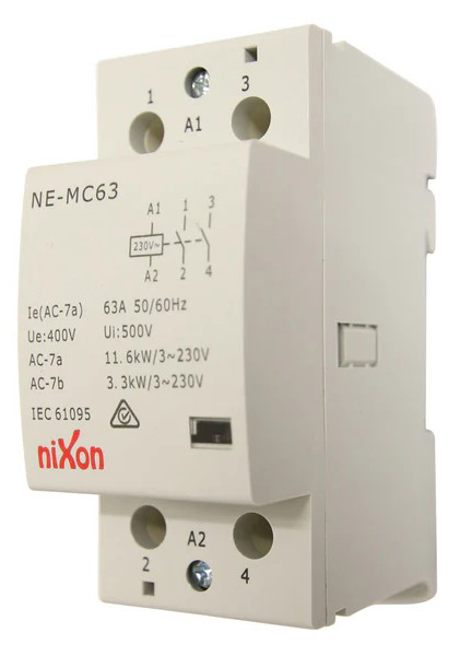
A main contactor, manufactured by NIXON, is an electromechanical switch used for switching an electrical power circuit. It is similar to a relay but is designed to handle higher current loads and is thus commonly used in industrial and commercial electrical systems. Main contactors are essential components in controlling the flow of electricity in heavy machinery, motor controllers, lighting systems, and heating, ventilation, and air conditioning (HVAC) applications.

Explore Projects Built with MAIN CONTACTOR

Use Cirkit Designer to design, explore, and prototype these projects online. Some projects support real-time simulation. Click "Open Project" to start designing instantly!
Industrial Power Distribution and Safety Control System
Image of Control Diagram: A project utilizing MAIN CONTACTOR in a practical application
This circuit is designed for power distribution and safety control in an industrial setting. It features a main isolator and circuit breaker for power management, multiple PSUs for 5V, 12V, and 24V outputs, and a safety relay system that interfaces with E-stop buttons and a start switch to control a main contactor, ensuring safe operation and emergency power cut-off capabilities.
Cirkit Designer LogoOpen Project in Cirkit Designer
Electromechanical Pump Control Circuit with Emergency Stop
Image of Pelton.: A project utilizing MAIN CONTACTOR in a practical application
This circuit is designed to control a pump using a contactor that is manually operated by a switch and can be overridden by an emergency stop. The contactor enables power from an AC power outlet to the pump, and the emergency stop can interrupt the power circuit for safety purposes.
Cirkit Designer LogoOpen Project in Cirkit Designer
Battery-Powered Emergency Alert System with NUCLEO-F072RB, SIM800L, and GPS NEO 6M
Image of women safety: A project utilizing MAIN CONTACTOR in a practical application
This circuit is an emergency alert system that uses a NUCLEO-F072RB microcontroller to send SMS alerts and make calls via a SIM800L GSM module, while obtaining location data from a GPS NEO 6M module. The system is powered by a Li-ion battery and includes a TP4056 module for battery charging and protection, with a rocker switch to control power to the microcontroller.
Cirkit Designer LogoOpen Project in Cirkit Designer
ESP32-Based Smart Arena System with IR Sensor, Keypad, and OLED Display
Image of AUTO ARENA TURF: A project utilizing MAIN CONTACTOR in a practical application
This circuit is an automated control system featuring an ESP32 microcontroller, which interfaces with an IR sensor, a 4x4 membrane keypad, a servo motor, an OLED display, a buzzer, and two 12V relays. The system detects objects using the IR sensor, displays messages on the OLED, and responds to keypad inputs to control the relays and servo motor, with additional auditory feedback provided by the buzzer.
Cirkit Designer LogoOpen Project in Cirkit Designer

Explore Projects Built with MAIN CONTACTOR

Use Cirkit Designer to design, explore, and prototype these projects online. Some projects support real-time simulation. Click "Open Project" to start designing instantly!
Image of Control Diagram: A project utilizing MAIN CONTACTOR in a practical application
Industrial Power Distribution and Safety Control System
This circuit is designed for power distribution and safety control in an industrial setting. It features a main isolator and circuit breaker for power management, multiple PSUs for 5V, 12V, and 24V outputs, and a safety relay system that interfaces with E-stop buttons and a start switch to control a main contactor, ensuring safe operation and emergency power cut-off capabilities.
Cirkit Designer LogoOpen Project in Cirkit Designer
Image of Pelton.: A project utilizing MAIN CONTACTOR in a practical application
Electromechanical Pump Control Circuit with Emergency Stop
This circuit is designed to control a pump using a contactor that is manually operated by a switch and can be overridden by an emergency stop. The contactor enables power from an AC power outlet to the pump, and the emergency stop can interrupt the power circuit for safety purposes.
Cirkit Designer LogoOpen Project in Cirkit Designer
Image of women safety: A project utilizing MAIN CONTACTOR in a practical application
Battery-Powered Emergency Alert System with NUCLEO-F072RB, SIM800L, and GPS NEO 6M
This circuit is an emergency alert system that uses a NUCLEO-F072RB microcontroller to send SMS alerts and make calls via a SIM800L GSM module, while obtaining location data from a GPS NEO 6M module. The system is powered by a Li-ion battery and includes a TP4056 module for battery charging and protection, with a rocker switch to control power to the microcontroller.
Cirkit Designer LogoOpen Project in Cirkit Designer
Image of AUTO ARENA TURF: A project utilizing MAIN CONTACTOR in a practical application
ESP32-Based Smart Arena System with IR Sensor, Keypad, and OLED Display
This circuit is an automated control system featuring an ESP32 microcontroller, which interfaces with an IR sensor, a 4x4 membrane keypad, a servo motor, an OLED display, a buzzer, and two 12V relays. The system detects objects using the IR sensor, displays messages on the OLED, and responds to keypad inputs to control the relays and servo motor, with additional auditory feedback provided by the buzzer.
Cirkit Designer LogoOpen Project in Cirkit Designer

Technical Specifications

General Characteristics

  • Manufacturer: NIXON
  • Component Type: Main Contactor
  • Control Voltage: Typically ranges from 24V to 480V AC/DC
  • Rated Operational Current: Up to several hundred amperes (exact value to be specified)
  • Rated Operational Voltage: Up to 600V AC
  • Frequency: 50/60 Hz
  • Number of Poles: 3 or 4 poles (common configurations)
  • Contact Material: Silver alloy or similar high-conductivity, high-wear material
  • Mechanical Life: Several million operations
  • Electrical Life: Depends on load and operating conditions

Pin Configuration and Descriptions

Pin Number Description Notes
A1 Coil input (+) Control voltage positive terminal
A2 Coil input (-) Control voltage negative terminal
1, 3, 5 Power input terminals (L1, L2, L3) Connect to power source
2, 4, 6 Power output terminals (T1, T2, T3) Connect to load
NC Normally closed auxiliary contact Optional, for feedback or interlocking
NO Normally open auxiliary contact Optional, for feedback or interlocking

Note: The pin configuration may vary depending on the specific model and manufacturer. Always refer to the manufacturer's datasheet for exact details.

Usage Instructions

Integration into a Circuit

  1. Power Source Connection: Connect the power source lines to the input terminals (1, 3, 5) of the contactor.
  2. Load Connection: Connect the load to the output terminals (2, 4, 6) of the contactor.
  3. Control Signal: Apply the control voltage to the coil terminals (A1 and A2) to engage the contactor.

Best Practices

  • Ensure that the contactor's ratings match or exceed the requirements of the application.
  • Use appropriate cable sizes to handle the current without overheating.
  • Install a surge suppressor or varistor across the coil terminals to protect against voltage spikes.
  • Regularly inspect the contactor for signs of wear or damage, especially the contacts and coil.
  • Provide adequate ventilation to prevent overheating during operation.

Troubleshooting and FAQs

Common Issues

  • Contactor Does Not Engage: Check control voltage and coil connections. Ensure that the coil is not damaged.
  • Excessive Noise or Chatter: Verify that the control voltage is stable and within the specified range.
  • Contacts Not Closing Properly: Inspect for physical damage or debris. Consider replacing the contactor if contacts are worn out.

FAQs

Q: Can a main contactor be used for DC applications? A: Yes, but ensure that the contactor is rated for DC operation, as AC and DC ratings may differ.

Q: How do I know if the contactor coil is energized? A: Some contactors have an indicator or an auxiliary contact that can be used to signal when the coil is energized.

Q: What is the purpose of auxiliary contacts? A: Auxiliary contacts are used for signaling, interlocking circuits, or adding additional control logic.

Example Code for Arduino UNO

The following example demonstrates how to control a NIXON main contactor using an Arduino UNO. The Arduino can be used to switch the contactor on and off with a digital output pin connected to a relay module that is interfaced with the contactor's coil.

// Define the pin connected to the relay module
const int relayPin = 7;

void setup() {
  // Set the relay pin as an output
  pinMode(relayPin, OUTPUT);
}

void loop() {
  // Turn on the contactor (relay module activation)
  digitalWrite(relayPin, HIGH);
  delay(5000); // Keep the contactor on for 5 seconds

  // Turn off the contactor (relay module deactivation)
  digitalWrite(relayPin, LOW);
  delay(5000); // Keep the contactor off for 5 seconds
}

Note: The above code assumes the use of a relay module that is compatible with the Arduino's 5V logic level. The relay module should be capable of handling the control voltage required by the contactor's coil.

Important: Always ensure that the relay module used is rated for the contactor's coil voltage and current. Directly connecting the contactor to the Arduino without a relay module can damage the microcontroller.