
How to Use BLDC Driver 24W, 5-40V, 2A: Examples, Pinouts, and Specs
 Design with BLDC Driver 24W, 5-40V, 2A in Cirkit Designer
Introduction
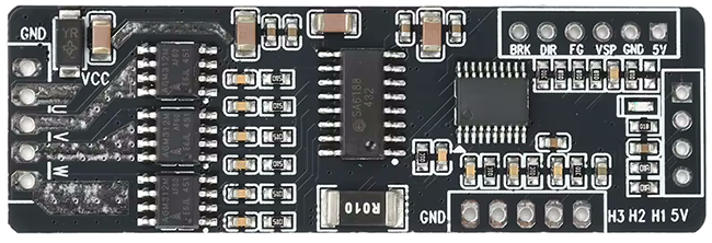
The BLDC Driver 24W by GREATZT (Part ID: BLDC Driver 24W) is a compact and efficient motor driver designed for controlling Brushless DC (BLDC) motors. It operates at a power rating of 24 watts, supports input voltages ranging from 5V to 40V, and can handle a maximum current of 2A. This driver is ideal for applications requiring precise motor control, such as robotics, drones, electric vehicles, and industrial automation systems.
Explore Projects Built with BLDC Driver 24W, 5-40V, 2A
 Open Project in Cirkit Designer
 Open Project in Cirkit Designer
 Open Project in Cirkit Designer
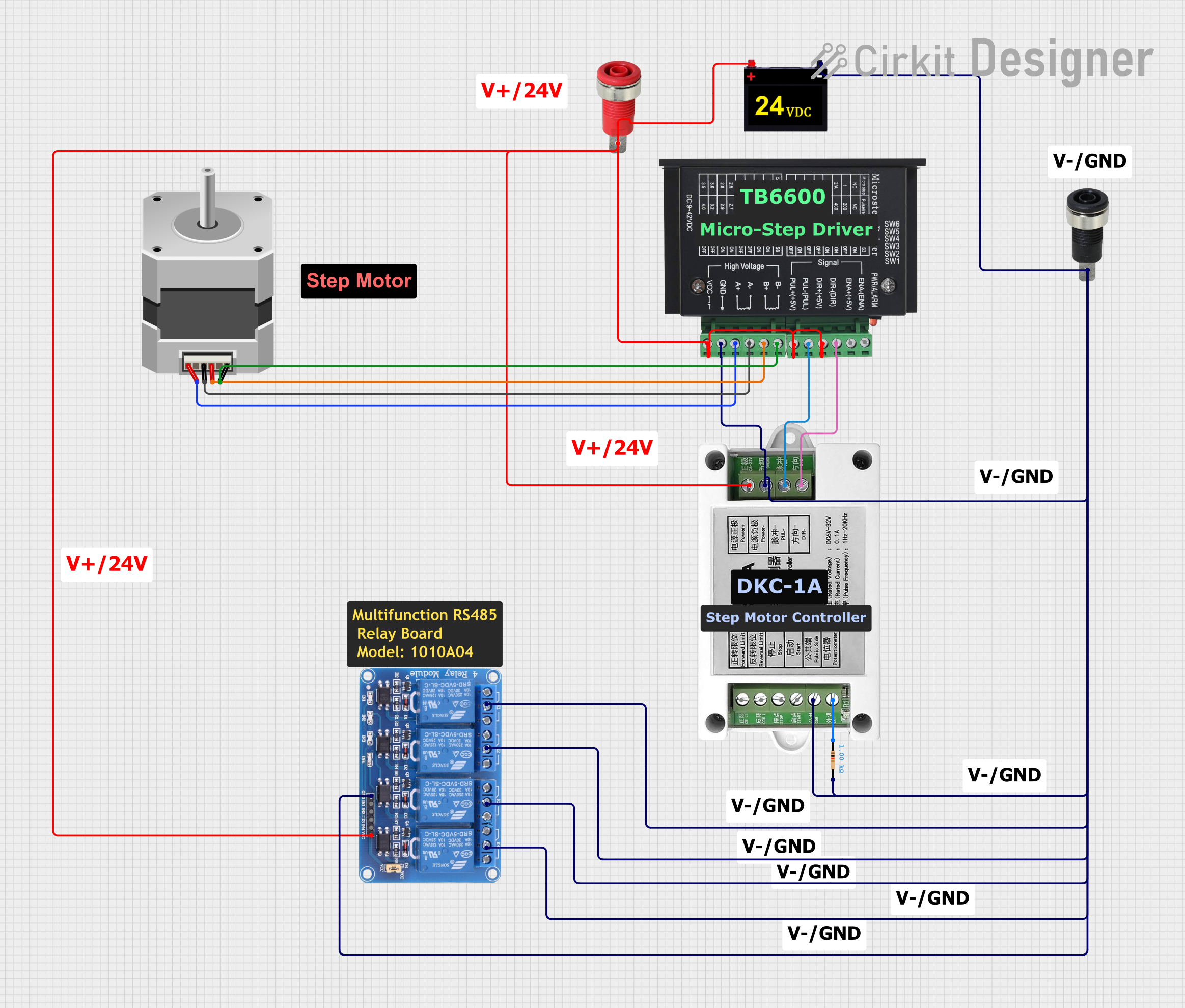 Open Project in Cirkit Designer
Explore Projects Built with BLDC Driver 24W, 5-40V, 2A
Open Project in Cirkit DesignerOpen Project in Cirkit DesignerOpen Project in Cirkit DesignerOpen Project in Cirkit DesignerCommon Applications
- Robotics and automation systems
- Electric scooters and drones
- Industrial machinery
- HVAC systems
- DIY motor control projects
Technical Specifications
Key Specifications
| Parameter | Value |
|---|---|
| Manufacturer | GREATZT |
| Part ID | BLDC Driver 24W |
| Input Voltage Range | 5V to 40V |
| Maximum Current | 2A |
| Power Rating | 24W |
| Motor Type Supported | Brushless DC (BLDC) |
| Control Modes | Speed and direction control |
| Operating Temperature | -20°C to 85°C |
| Dimensions | 50mm x 30mm x 15mm |
Pin Configuration and Descriptions
The BLDC Driver 24W module features a simple pinout for easy integration into circuits. Below is the pin configuration:
| Pin Name | Pin Type | Description |
|---|---|---|
| VIN | Power Input | Connect to the positive terminal of the power supply (5-40V). |
| GND | Power Ground | Connect to the ground terminal of the power supply. |
| U, V, W | Motor Outputs | Connect to the three-phase wires of the BLDC motor. |
| EN | Input Signal | Enable pin; HIGH to enable the driver, LOW to disable it. |
| PWM | Input Signal | Pulse Width Modulation input for speed control. |
| DIR | Input Signal | Direction control; HIGH for forward, LOW for reverse. |
| FG | Output Signal | Feedback signal for motor speed monitoring. |
Usage Instructions
How to Use the BLDC Driver 24W in a Circuit
Power Supply Connection:
- Connect the VIN pin to a DC power supply (5V to 40V) capable of providing sufficient current for your motor.
- Connect the GND pin to the ground of the power supply.
Motor Connection:
- Connect the U, V, and W pins to the corresponding three-phase wires of your BLDC motor. Ensure the connections are secure to avoid interruptions.
Control Signals:
- Use the EN pin to enable or disable the driver. Pull it HIGH to enable the driver.
- Provide a PWM signal to the PWM pin to control the motor speed. The duty cycle of the PWM signal determines the speed.
- Use the DIR pin to set the motor's rotation direction. Pull it HIGH for forward rotation and LOW for reverse rotation.
Feedback Monitoring:
- The FG pin outputs a feedback signal proportional to the motor's speed. This can be used for closed-loop control or monitoring.
Important Considerations and Best Practices
- Ensure the power supply voltage matches the motor's operating voltage range.
- Do not exceed the maximum current rating of 2A to avoid damaging the driver.
- Use appropriate heat dissipation methods (e.g., heatsinks) if operating at high currents for extended periods.
- Verify the motor's wiring and ensure it matches the U, V, and W outputs of the driver.
- Use a microcontroller (e.g., Arduino) to generate precise PWM and DIR signals for better control.
Example: Using the BLDC Driver 24W with Arduino UNO
Below is an example Arduino sketch to control the BLDC motor using the BLDC Driver 24W:
// Define pin connections
const int enablePin = 7;  // Connect to EN pin of the driver
const int pwmPin = 6;     // Connect to PWM pin of the driver
const int dirPin = 5;     // Connect to DIR pin of the driver

void setup() {
  // Set pin modes
  pinMode(enablePin, OUTPUT);
  pinMode(pwmPin, OUTPUT);
  pinMode(dirPin, OUTPUT);

  // Enable the driver
  digitalWrite(enablePin, HIGH);

  // Set initial direction to forward
  digitalWrite(dirPin, HIGH);
}

void loop() {
  // Gradually increase motor speed
  for (int speed = 0; speed <= 255; speed++) {
    analogWrite(pwmPin, speed); // Set PWM duty cycle (0-255)
    delay(20);                  // Small delay for smooth acceleration
  }

  delay(2000); // Run at full speed for 2 seconds

  // Gradually decrease motor speed
  for (int speed = 255; speed >= 0; speed--) {
    analogWrite(pwmPin, speed);
    delay(20);
  }

  delay(2000); // Pause before reversing direction

  // Reverse direction
  digitalWrite(dirPin, LOW);

  // Repeat the same speed control process in reverse direction
  for (int speed = 0; speed <= 255; speed++) {
    analogWrite(pwmPin, speed);
    delay(20);
  }

  delay(2000);

  for (int speed = 255; speed >= 0; speed--) {
    analogWrite(pwmPin, speed);
    delay(20);
  }

  delay(2000); // Pause before switching direction again
}
Troubleshooting and FAQs
Common Issues and Solutions
Motor Does Not Spin:
- Ensure the power supply is connected and providing the correct voltage.
- Verify that the EN pin is pulled HIGH to enable the driver.
- Check the motor connections (U, V, W) and ensure they are secure.
Motor Spins in the Wrong Direction:
- Check the DIR pin signal. Pull it HIGH for forward rotation and LOW for reverse.
Motor Speed is Unstable:
- Ensure the PWM signal is stable and within the correct frequency range (typically 1kHz to 20kHz).
- Verify that the power supply can provide sufficient current for the motor.
Driver Overheats:
- Ensure the current drawn by the motor does not exceed 2A.
- Use a heatsink or active cooling if operating at high currents for extended periods.
FAQs
Q: Can I use this driver with a sensorless BLDC motor?
A: Yes, the BLDC Driver 24W supports sensorless BLDC motors. However, ensure proper tuning of the control signals for optimal performance.
Q: What is the recommended PWM frequency for speed control?
A: A PWM frequency between 1kHz and 20kHz is recommended for smooth motor operation.
Q: Can I use this driver with a 12V power supply?
A: Yes, the driver supports input voltages from 5V to 40V, so a 12V power supply is compatible.
Q: How do I monitor the motor's speed?
A: Use the FG pin, which outputs a feedback signal proportional to the motor's speed. This signal can be read using a microcontroller or frequency counter.