
How to Use ADG728 Matrix Switch: Examples, Pinouts, and Specs
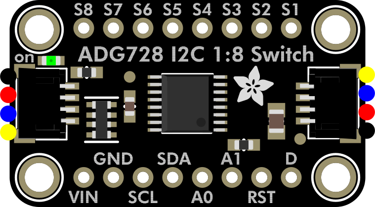
 Design with ADG728 Matrix Switch in Cirkit Designer
Introduction
The ADG728 is a dual 4-channel analog switch manufactured by Adafruit. It is designed for switching multiple analog signals in a matrix configuration, offering low on-resistance, high-speed switching, and low power consumption. This makes it an ideal choice for applications requiring efficient signal routing, such as telecommunications, audio systems, and data acquisition systems.
Explore Projects Built with ADG728 Matrix Switch
 Open Project in Cirkit Designer
 Open Project in Cirkit Designer
 Open Project in Cirkit Designer
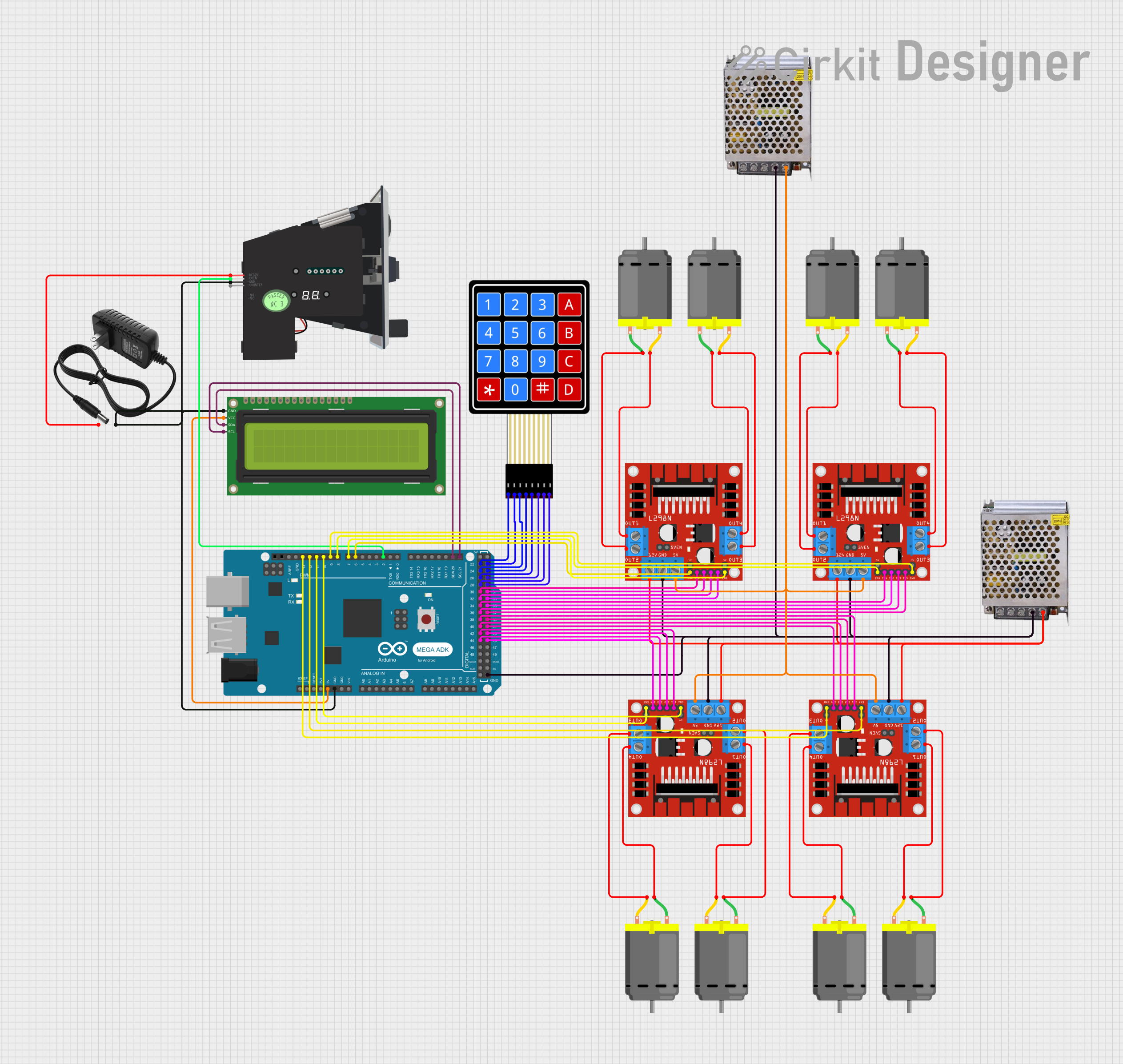 Open Project in Cirkit Designer
Explore Projects Built with ADG728 Matrix Switch
Open Project in Cirkit DesignerOpen Project in Cirkit DesignerOpen Project in Cirkit DesignerOpen Project in Cirkit DesignerCommon Applications
- Audio signal routing and mixing
- Data acquisition systems
- Telecommunication systems
- Test and measurement equipment
- Sensor multiplexing
Technical Specifications
Key Technical Details
- Manufacturer: Adafruit
- Switch Configuration: Dual 4-channel (8:1 matrix)
- Supply Voltage Range: 2.7 V to 5.5 V
- On-Resistance (RON): 2.5 Ω (typical)
- Switching Time: 20 ns (typical)
- Power Consumption: Low power, <1 µA in standby mode
- Control Interface: I²C-compatible
- Operating Temperature Range: -40°C to +85°C
Pin Configuration and Descriptions
The ADG728 is typically available in a 16-lead TSSOP package. Below is the pin configuration:
| Pin Number | Pin Name | Description |
|---|---|---|
| 1 | SCL | I²C clock input |
| 2 | SDA | I²C data input/output |
| 3 | A0 | I²C address selection pin |
| 4 | A1 | I²C address selection pin |
| 5 | GND | Ground |
| 6-9 | S1A-S4A | Analog switch inputs for channel A |
| 10-13 | S1B-S4B | Analog switch inputs for channel B |
| 14 | D1 | Common output for channel A |
| 15 | D2 | Common output for channel B |
| 16 | VDD | Positive power supply |
Usage Instructions
How to Use the ADG728 in a Circuit
- Power Supply: Connect the VDD pin to a power supply within the range of 2.7 V to 5.5 V. Connect the GND pin to the ground of the circuit.
- I²C Interface: Use the SCL and SDA pins to communicate with the ADG728 via an I²C-compatible microcontroller. Configure the I²C address using the A0 and A1 pins.
- Signal Connections: Connect the analog signals to the S1A-S4A and S1B-S4B pins. The selected signals will be routed to the D1 and D2 pins, respectively.
- Control: Use I²C commands to select the desired switch configuration. Each channel can be independently controlled.
Important Considerations
- Signal Voltage Range: Ensure that the input signal voltage does not exceed the supply voltage (VDD).
- I²C Pull-Up Resistors: Use appropriate pull-up resistors on the SCL and SDA lines for proper I²C communication.
- Decoupling Capacitor: Place a 0.1 µF decoupling capacitor close to the VDD pin to reduce noise and improve stability.
Example Code for Arduino UNO
Below is an example of how to control the ADG728 using an Arduino UNO:
#include <Wire.h> // Include the Wire library for I²C communication

#define ADG728_ADDR 0x70 // Default I²C address of the ADG728

void setup() {
  Wire.begin(); // Initialize I²C communication
  Serial.begin(9600); // Initialize serial communication for debugging

  // Select channel 1A (S1A to D1)
  selectChannel(0x01); // 0x01 corresponds to channel 1A
}

void loop() {
  // Main loop can be used to switch channels dynamically
}

// Function to select a specific channel on the ADG728
void selectChannel(uint8_t channel) {
  Wire.beginTransmission(ADG728_ADDR); // Start communication with ADG728
  Wire.write(channel); // Send the channel selection command
  Wire.endTransmission(); // End communication

  Serial.print("Channel selected: ");
  Serial.println(channel, HEX); // Print the selected channel for debugging
}
Explanation of Code
- The
Wire.begin()function initializes the I²C communication. - The
selectChannel()function sends a command to the ADG728 to select a specific channel. The channel is specified as a hexadecimal value (e.g.,0x01for channel 1A).
Troubleshooting and FAQs
Common Issues and Solutions
No Response from the ADG728
- Cause: Incorrect I²C address or wiring.
- Solution: Verify the I²C address and ensure proper connections to the SCL and SDA pins. Check the pull-up resistors on the I²C lines.
Signal Distortion
- Cause: Input signal exceeds the supply voltage or poor grounding.
- Solution: Ensure the input signal voltage is within the VDD range. Check the ground connections and add a decoupling capacitor near the VDD pin.
Switch Not Changing Channels
- Cause: Incorrect I²C command or communication failure.
- Solution: Double-check the I²C commands being sent. Use a logic analyzer to monitor the I²C communication.
FAQs
Q1: Can the ADG728 handle digital signals?
A1: Yes, the ADG728 can switch both analog and digital signals, provided the signal voltage is within the supply voltage range.
Q2: How many devices can be connected on the same I²C bus?
A2: Up to 4 ADG728 devices can be connected on the same I²C bus by configuring the A0 and A1 address pins.
Q3: What is the maximum signal frequency the ADG728 can handle?
A3: The ADG728 is suitable for signals up to 10 MHz, depending on the load and circuit configuration.
Q4: Is the ADG728 bidirectional?
A4: Yes, the ADG728 supports bidirectional signal flow, making it versatile for various applications.