How to Use can module: Examples, Pinouts, and Specs
Introduction
The Controller Area Network (CAN) module is a communication interface designed for reliable, real-time data exchange between microcontrollers and devices. It is widely used in automotive and industrial applications due to its robust design and ability to operate in noisy environments. The CAN module allows multiple devices to communicate efficiently without requiring a host computer, making it ideal for distributed systems.
Explore Projects Built with can module


Explore Projects Built with can module
Common Applications and Use Cases
- Automotive systems (e.g., engine control units, airbags, and infotainment systems)
- Industrial automation and control systems
- Robotics and embedded systems
- Medical devices
- IoT networks requiring robust communication
Technical Specifications
Below are the key technical details of a typical CAN module:
| Parameter | Value |
|---|---|
| Operating Voltage | 3.3V or 5V |
| Communication Protocol | CAN 2.0A/B, ISO 11898-1 compliant |
| Data Rate | Up to 1 Mbps |
| Operating Temperature | -40°C to +85°C |
| Interface | SPI (Serial Peripheral Interface) |
| Maximum Nodes Supported | 120 |
Pin Configuration and Descriptions
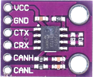
The CAN module typically uses an 8-pin configuration. Below is a table describing the pins:
| Pin | Name | Description |
|---|---|---|
| 1 | VCC | Power supply input (3.3V or 5V, depending on the module) |
| 2 | GND | Ground connection |
| 3 | CS | Chip Select pin for SPI communication |
| 4 | SCK | Serial Clock pin for SPI communication |
| 5 | MOSI | Master Out Slave In pin for SPI communication |
| 6 | MISO | Master In Slave Out pin for SPI communication |
| 7 | CAN_H | High line of the CAN bus |
| 8 | CAN_L | Low line of the CAN bus |
Usage Instructions
How to Use the CAN Module in a Circuit
- Power the Module: Connect the VCC pin to a 3.3V or 5V power source (as specified by your module) and the GND pin to the ground.
- Connect to a Microcontroller: Use the SPI pins (CS, SCK, MOSI, MISO) to interface the CAN module with a microcontroller, such as an Arduino UNO.
- Connect the CAN Bus: Attach the CAN_H and CAN_L pins to the corresponding lines of the CAN bus. Use a 120-ohm termination resistor at each end of the bus for proper signal integrity.
- Install Required Libraries: For Arduino, install the "MCP_CAN" library, which supports CAN communication.
- Write and Upload Code: Use the provided example code or write your own to initialize and communicate via the CAN bus.
Important Considerations and Best Practices
- Ensure the CAN bus is properly terminated with 120-ohm resistors at both ends.
- Match the module's operating voltage with the microcontroller to avoid damage.
- Use shielded twisted-pair cables for the CAN_H and CAN_L lines to minimize noise.
- Verify the baud rate of all devices on the CAN bus to ensure compatibility.
Example Code for Arduino UNO
Below is an example of how to use the CAN module with an Arduino UNO:
#include <SPI.h>
#include <mcp_can.h>

// Define the SPI Chip Select pin for the CAN module
#define CAN_CS 10

// Initialize the CAN module object
MCP_CAN CAN(CAN_CS);

void setup() {
  Serial.begin(115200); // Start serial communication for debugging
  while (!Serial);

  // Initialize the CAN module at 500 kbps
  if (CAN.begin(MCP_ANY, 500000, MCP_8MHZ) == CAN_OK) {
    Serial.println("CAN module initialized successfully!");
  } else {
    Serial.println("Error initializing CAN module. Check connections.");
    while (1);
  }

  // Set the CAN module to normal mode
  CAN.setMode(MCP_NORMAL);
  Serial.println("CAN module set to normal mode.");
}

void loop() {
  // Example: Send a message with ID 0x100 and 8 bytes of data
  byte data[8] = {0x01, 0x02, 0x03, 0x04, 0x05, 0x06, 0x07, 0x08};
  if (CAN.sendMsgBuf(0x100, 0, 8, data) == CAN_OK) {
    Serial.println("Message sent successfully!");
  } else {
    Serial.println("Error sending message.");
  }

  delay(1000); // Wait 1 second before sending the next message
}
Troubleshooting and FAQs
Common Issues and Solutions
CAN Module Not Initializing
- Cause: Incorrect wiring or power supply.
- Solution: Double-check the connections, ensure the module is powered correctly, and verify the SPI pins are connected properly.
No Communication on the CAN Bus
- Cause: Baud rate mismatch or missing termination resistors.
- Solution: Ensure all devices on the CAN bus use the same baud rate and that 120-ohm resistors are installed at both ends of the bus.
Noise or Data Corruption
- Cause: Poor wiring or lack of shielding.
- Solution: Use shielded twisted-pair cables for the CAN_H and CAN_L lines and keep the bus length within recommended limits.
FAQs
Q: Can I use the CAN module with a 3.3V microcontroller?
A: Yes, but ensure the module supports 3.3V operation. Some modules are compatible with both 3.3V and 5V systems.
Q: What is the maximum length of a CAN bus?
A: The maximum length depends on the baud rate. For example, at 1 Mbps, the maximum length is approximately 40 meters.
Q: Can I connect more than two devices to the CAN bus?
A: Yes, the CAN protocol supports up to 120 nodes on a single bus, provided the electrical characteristics are maintained.
Q: Do I need to install any libraries for Arduino?
A: Yes, you need the "MCP_CAN" library, which can be installed via the Arduino Library Manager.