How to Use Servomotor SG92R: Examples, Pinouts, and Specs

Introduction
The Servomotor SG92R is a compact and lightweight servo that is widely used in the realm of hobby electronics, robotics, and RC (radio-controlled) applications. It is particularly favored for its precision control, allowing users to rotate the output shaft to specific angles, typically ranging from 0 to 180 degrees. The SG92R is an affordable and versatile choice for projects that require controlled movement, such as robotic arms, steering mechanisms for vehicles, or animatronics.
Explore Projects Built with Servomotor SG92R
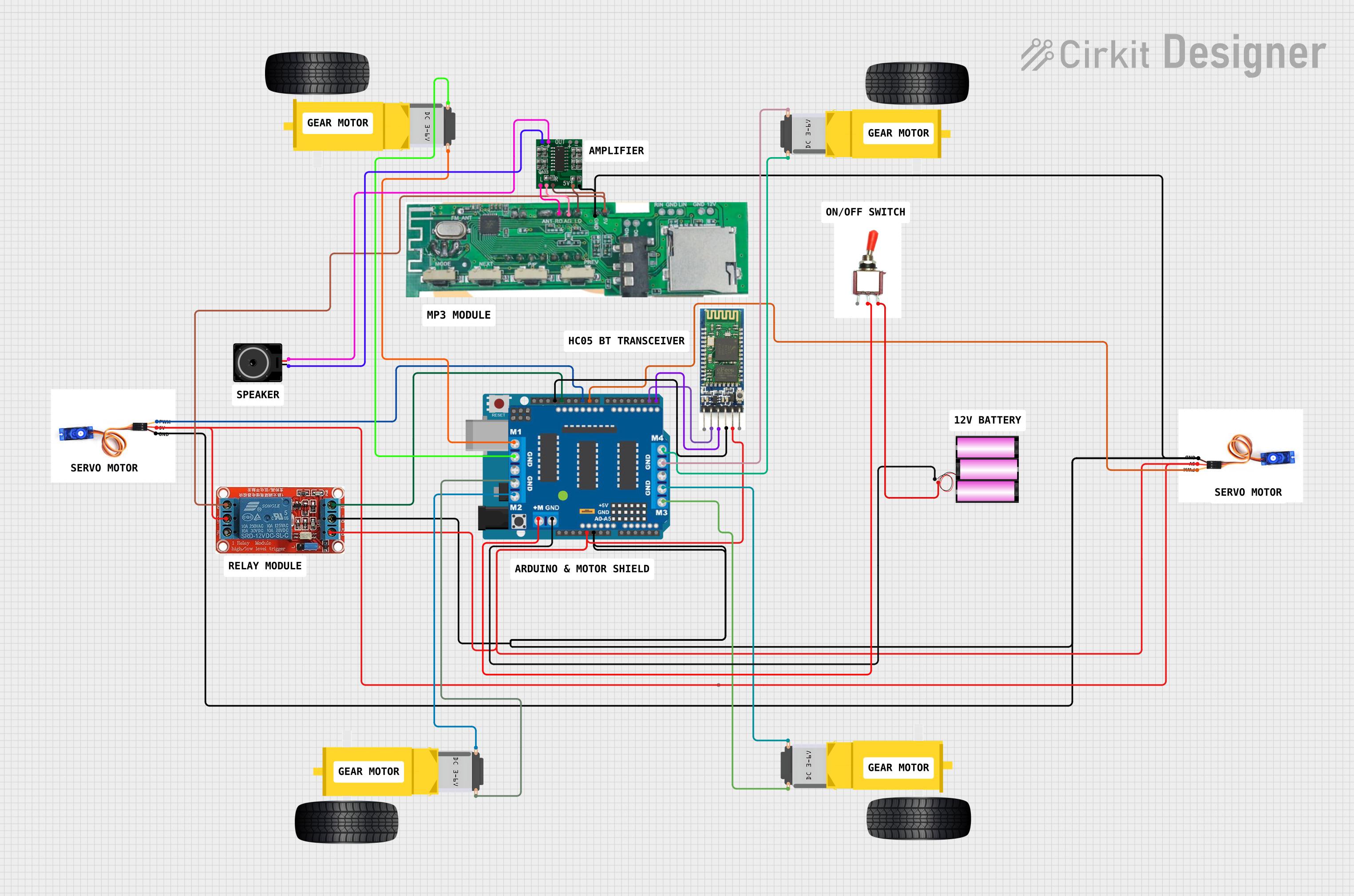
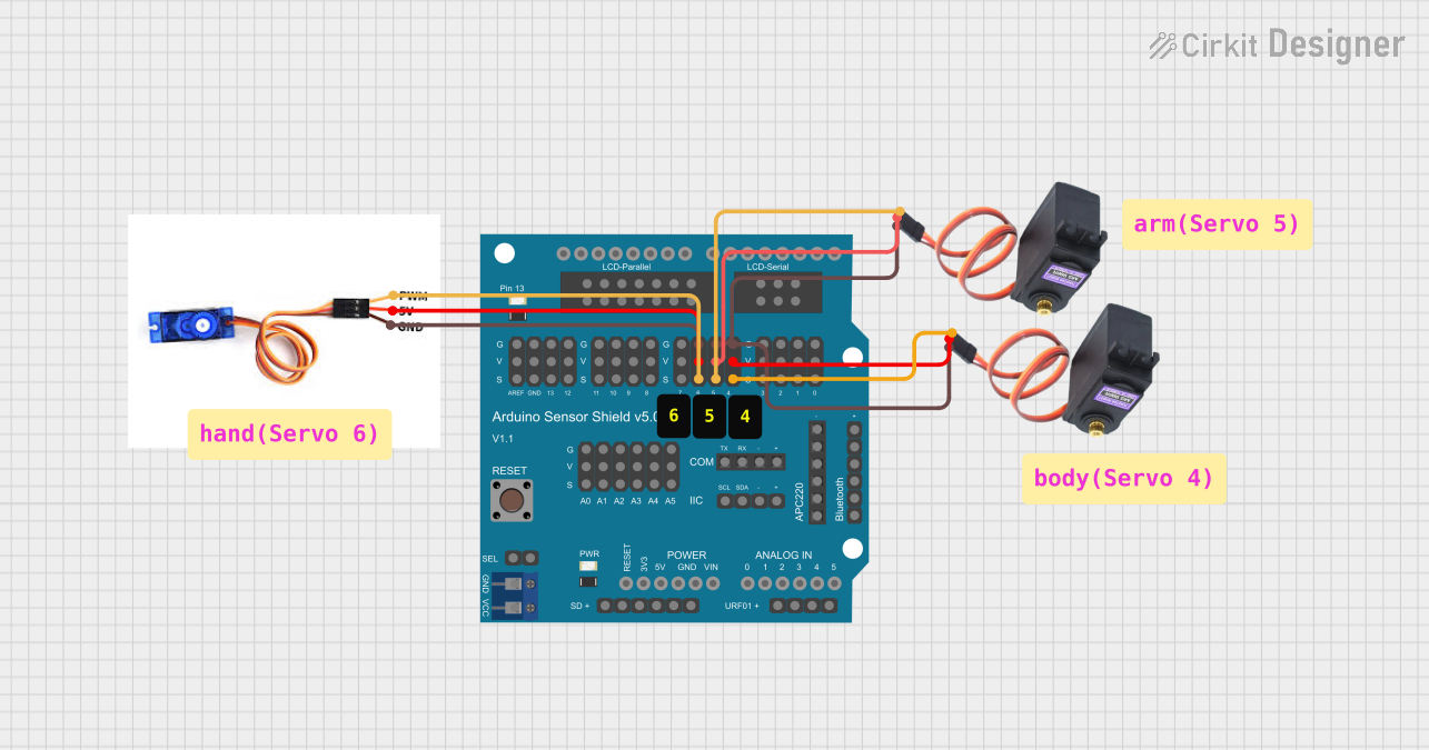
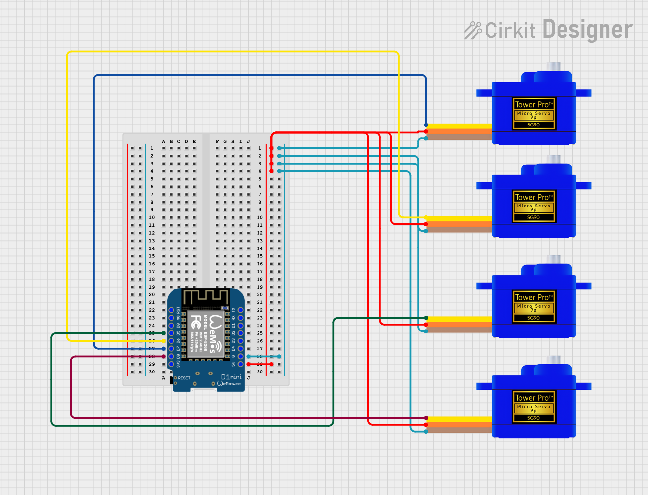
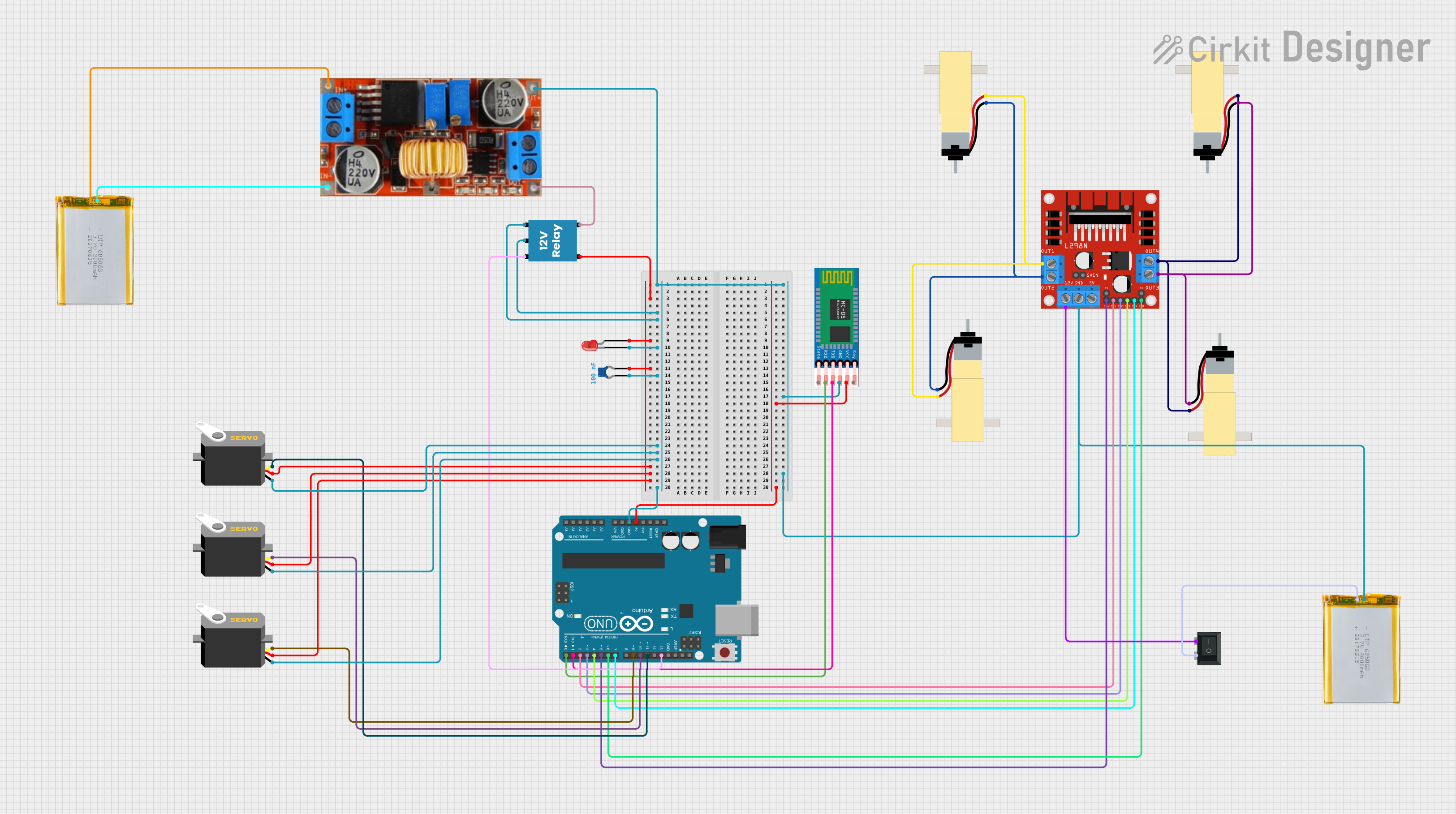
Explore Projects Built with Servomotor SG92R
Technical Specifications
Key Technical Details
- Operating Voltage: 4.8V to 6.0V
- Stall Torque: 2.5 kg-cm (4.8V), 2.8 kg-cm (6.0V)
- Operating Speed: 0.1 sec/60° (4.8V), 0.09 sec/60° (6.0V)
- Temperature Range: -30°C to +60°C
- Dead Band Width: 5 µs
- Weight: 9g
- Dimensions: 23.2 x 12.5 x 22 mm
Pin Configuration and Descriptions
| Pin Number | Color | Description |
|---|---|---|
| 1 | Brown | Ground (GND) |
| 2 | Red | Power Supply (VCC) |
| 3 | Orange | Control Signal (PWM) |
Usage Instructions
Connecting to a Circuit
- Power Supply (VCC): Connect the red wire to a power source that provides a voltage within the operating range of the servo (4.8V to 6.0V).
- Ground (GND): Connect the brown wire to the ground of your power supply and microcontroller.
- Control Signal (PWM): Connect the orange wire to a PWM-capable pin on your microcontroller.
Important Considerations and Best Practices
- Ensure that the power supply is capable of delivering sufficient current for the servo's operation, especially if multiple servos are used.
- Avoid stalling the servo at its end positions for extended periods, as this can lead to overheating and damage.
- Use a decoupling capacitor (e.g., 100 µF) between VCC and GND near the servo to stabilize the power supply.
- When controlling the servo from a microcontroller like an Arduino, use the
Servolibrary for easier implementation.
Example Code for Arduino UNO
#include <Servo.h>

Servo myservo;  // Create servo object to control the SG92R

void setup() {
  myservo.attach(9); // Attaches the servo on pin 9 to the servo object
}

void loop() {
  myservo.write(90); // Sets the servo position to 90°
  delay(1000);       // Wait for 1 second
  myservo.write(0);  // Sets the servo position to 0°
  delay(1000);       // Wait for 1 second
}
Troubleshooting and FAQs
Common Issues
- Servo not responding: Check the wiring and ensure that the control signal is connected to a PWM-capable pin. Also, verify that the power supply is within the specified voltage range and can provide adequate current.
- Erratic movement or jitter: This can be caused by an insufficient power supply, interference on the control signal, or a damaged servo. Ensure the power supply is stable and use a decoupling capacitor. Check the control signal wire for damage or loose connections.
- Overheating: Continuous operation at stall torque or excessive load can cause overheating. Reduce the load or duty cycle to allow the servo to cool down.
FAQs
Q: Can I control the SG92R with a Raspberry Pi?
- A: Yes, but you will need to generate PWM signals, which can be done using software or an external PWM driver module.
Q: How do I calibrate the servo for precise angles?
- A: Use the
writeMicroseconds()function in the ArduinoServolibrary to fine-tune the pulse width for accurate positioning.
- A: Use the
Q: What is the maximum angle the SG92R can rotate?
- A: The SG92R typically has a rotation range of 0 to 180 degrees, but the actual range may vary slightly from one servo to another.
Remember to always refer to the manufacturer's datasheet for the most accurate and detailed information about the SG92R servomotor.