How to Use MAX3232 RS232 to TTL Serial Port Converter Module: Examples, Pinouts, and Specs
Introduction
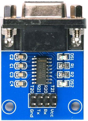
The MAX3232 is a dual driver/receiver module designed to convert RS-232 signals to TTL (Transistor-Transistor Logic) levels and vice versa. It enables seamless communication between devices operating at different voltage levels, such as microcontrollers and RS-232 peripherals. The module is widely used in serial communication applications, offering reliable data transmission over longer distances.
Explore Projects Built with MAX3232 RS232 to TTL Serial Port Converter Module


Explore Projects Built with MAX3232 RS232 to TTL Serial Port Converter Module
Common Applications and Use Cases
- Interfacing microcontrollers (e.g., Arduino, Raspberry Pi) with RS-232 devices such as modems, GPS modules, and industrial equipment.
- Serial communication in embedded systems.
- Debugging and testing RS-232 devices.
- Extending communication range in serial data transmission.
Technical Specifications
Key Technical Details
- Operating Voltage: 3.0V to 5.5V DC.
- RS-232 Voltage Levels: ±3V to ±15V.
- TTL Voltage Levels: 0V to 5V (compatible with 3.3V and 5V logic).
- Baud Rate: Up to 250 kbps.
- Number of Drivers/Receivers: 2 drivers and 2 receivers.
- Operating Temperature: -40°C to +85°C.
- Power Consumption: Low power, with automatic shutdown feature.
Pin Configuration and Descriptions
The MAX3232 module typically has a 6-pin header for TTL connections and a DB9 connector for RS-232 connections. Below is the pinout for the TTL header:
| Pin | Name | Description |
|---|---|---|
| 1 | VCC | Power supply input (3.0V to 5.5V). |
| 2 | GND | Ground connection. |
| 3 | TXD | TTL Transmit Data (connect to RXD of the microcontroller). |
| 4 | RXD | TTL Receive Data (connect to TXD of the microcontroller). |
| 5 | CTS | Clear to Send (optional, used for hardware flow control). |
| 6 | RTS | Request to Send (optional, used for hardware flow control). |
The DB9 connector pinout follows the standard RS-232 configuration, with pins for TX, RX, GND, and flow control signals.
Usage Instructions
How to Use the MAX3232 in a Circuit
- Power the Module: Connect the VCC pin to a 3.3V or 5V power source and the GND pin to ground.
- Connect TTL Signals:
- Connect the TXD pin of the MAX3232 to the RXD pin of your microcontroller.
- Connect the RXD pin of the MAX3232 to the TXD pin of your microcontroller.
- Connect RS-232 Signals: Use the DB9 connector to interface with the RS-232 device.
- Optional Flow Control: If your application requires hardware flow control, connect the CTS and RTS pins as needed.
- Verify Connections: Double-check all connections to ensure proper operation.
Important Considerations and Best Practices
- Ensure the operating voltage of the module matches the logic level of your microcontroller (3.3V or 5V).
- Use short, high-quality cables for TTL connections to minimize noise and signal degradation.
- If hardware flow control is not required, leave the CTS and RTS pins unconnected.
- Avoid connecting the module to RS-232 devices with voltage levels exceeding ±15V.
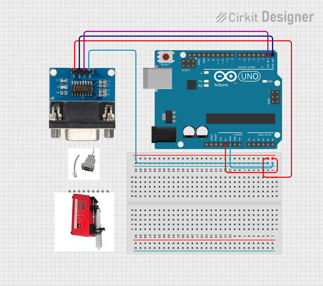
Example: Connecting to an Arduino UNO
Below is an example of how to use the MAX3232 module with an Arduino UNO to communicate with an RS-232 device.
Circuit Diagram
- Connect the MAX3232's VCC to the Arduino's 5V pin.
- Connect the MAX3232's GND to the Arduino's GND.
- Connect the MAX3232's TXD to the Arduino's RX (pin 0).
- Connect the MAX3232's RXD to the Arduino's TX (pin 1).
Arduino Code
// Example code for using MAX3232 with Arduino UNO
// This code sends and receives data over RS-232 using the Serial interface.

void setup() {
  Serial.begin(9600); // Initialize serial communication at 9600 baud
  delay(1000); // Wait for the RS-232 device to initialize
  Serial.println("MAX3232 RS-232 Communication Initialized");
}

void loop() {
  // Check if data is available from the RS-232 device
  if (Serial.available() > 0) {
    char receivedData = Serial.read(); // Read a character from RS-232
    Serial.print("Received: ");
    Serial.println(receivedData); // Print the received data to the Serial Monitor
  }

  // Send data to the RS-232 device
  Serial.println("Hello from Arduino!"); // Send a test message
  delay(1000); // Wait 1 second before sending the next message
}
Troubleshooting and FAQs
Common Issues and Solutions
No Data Transmission or Reception:
- Verify that the TXD and RXD pins are correctly connected (crossed: TXD to RXD, RXD to TXD).
- Ensure the baud rate in your code matches the RS-232 device's baud rate.
- Check the power supply voltage (3.3V or 5V) and ensure it is stable.
Corrupted Data:
- Use shorter cables for TTL connections to reduce noise.
- Verify that the RS-232 device's voltage levels are within the module's supported range (±3V to ±15V).
Module Overheating:
- Ensure the RS-232 device does not exceed the module's voltage and current ratings.
- Check for proper ventilation and avoid operating the module in high-temperature environments.
Flow Control Issues:
- If not using hardware flow control, ensure the CTS and RTS pins are left unconnected.
- If using flow control, verify that the RS-232 device supports it and that the connections are correct.
FAQs
Q: Can the MAX3232 module work with 3.3V microcontrollers?
A: Yes, the MAX3232 is compatible with both 3.3V and 5V logic levels.
Q: What is the maximum communication distance supported by the MAX3232?
A: The RS-232 standard supports communication distances of up to 15 meters (50 feet), depending on the baud rate and cable quality.
Q: Do I need external capacitors for the MAX3232 module?
A: No, most MAX3232 modules come with onboard capacitors for voltage level conversion, so no additional components are required.
Q: Can I use the MAX3232 with USB-to-Serial adapters?
A: Yes, the MAX3232 can interface with USB-to-Serial adapters that support RS-232 voltage levels.