
How to Use relay_5V: Examples, Pinouts, and Specs
 Design with relay_5V in Cirkit Designer
Introduction
A 5V relay is an electromechanical switch that uses an electromagnetic coil to open or close its internal contacts. This allows a low voltage signal (5V) to control high voltage or high current circuits safely and efficiently. Relays are widely used in applications where electrical isolation is required between the control circuit and the load circuit.
Explore Projects Built with relay_5V
 Open Project in Cirkit Designer
 Open Project in Cirkit Designer
 Open Project in Cirkit Designer
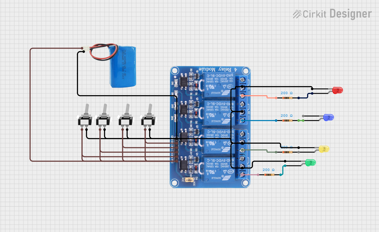 Open Project in Cirkit Designer
Explore Projects Built with relay_5V
Open Project in Cirkit DesignerOpen Project in Cirkit DesignerOpen Project in Cirkit DesignerOpen Project in Cirkit DesignerCommon Applications and Use Cases
- Home automation systems (e.g., controlling lights, fans, or appliances)
- Industrial control systems
- Motor control circuits
- Automotive electronics
- Microcontroller-based projects (e.g., Arduino, Raspberry Pi)
Technical Specifications
Key Technical Details
- Operating Voltage (Coil): 5V DC
- Trigger Current (Coil): ~70-100 mA
- Contact Ratings:
- Maximum Voltage: 250V AC / 30V DC
- Maximum Current: 10A
- Contact Type: SPDT (Single Pole Double Throw) or DPDT (Double Pole Double Throw), depending on the relay model
- Insulation Resistance: ≥ 100MΩ at 500V DC
- Dielectric Strength: 1500V AC (between coil and contacts)
- Switching Time:
- Operate Time: ~10 ms
- Release Time: ~5 ms
- Mechanical Life: ~10 million operations
- Electrical Life: ~100,000 operations (at rated load)
Pin Configuration and Descriptions
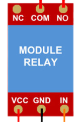
The 5V relay typically has 5 pins for SPDT relays. Below is the pin configuration:
| Pin Name | Description |
|---|---|
| Coil+ | Positive terminal of the electromagnetic coil (connect to 5V DC). |
| Coil- | Negative terminal of the electromagnetic coil (connect to ground). |
| Common (COM) | Common terminal for the relay's switching contacts. |
| Normally Open (NO) | Contact that remains open when the relay is inactive. Closes when activated. |
| Normally Closed (NC) | Contact that remains closed when the relay is inactive. Opens when activated. |
Usage Instructions
How to Use the Component in a Circuit
Power the Relay Coil:
- Connect the
Coil+pin to a 5V DC power source. - Connect the
Coil-pin to ground. - Use a transistor or relay driver circuit to control the coil if the control signal comes from a microcontroller (e.g., Arduino).
- Connect the
Connect the Load:
- Identify whether your load should be connected to the
NOorNCterminal:- Use
NOif the load should be powered only when the relay is activated. - Use
NCif the load should be powered when the relay is inactive.
- Use
- Connect one terminal of the load to the
COMpin and the other terminal to the appropriate contact (NOorNC).
- Identify whether your load should be connected to the
Control the Relay:
- Apply a 5V signal to the relay coil to activate it. This will switch the contacts from their default state (
NCtoNO).
- Apply a 5V signal to the relay coil to activate it. This will switch the contacts from their default state (
Important Considerations and Best Practices
- Use a Flyback Diode: Always connect a flyback diode (e.g., 1N4007) across the relay coil terminals to protect the driving circuit from voltage spikes caused by the collapsing magnetic field when the relay is turned off.
- Avoid Overloading: Ensure the load connected to the relay does not exceed its rated voltage or current.
- Isolation: Use optocouplers or relay modules with built-in isolation for added safety when interfacing with microcontrollers.
- Power Supply: Ensure the power supply can provide sufficient current to drive the relay coil.
Example: Connecting a 5V Relay to an Arduino UNO
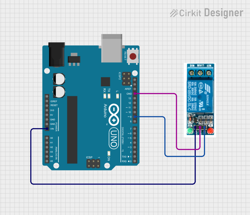
Below is an example of how to control a 5V relay using an Arduino UNO:
// Define the pin connected to the relay module
const int relayPin = 7;

void setup() {
  // Set the relay pin as an output
  pinMode(relayPin, OUTPUT);

  // Ensure the relay is off at startup
  digitalWrite(relayPin, LOW);
}

void loop() {
  // Turn the relay on (activates the NO contact)
  digitalWrite(relayPin, HIGH);
  delay(5000); // Keep the relay on for 5 seconds

  // Turn the relay off (deactivates the NO contact)
  digitalWrite(relayPin, LOW);
  delay(5000); // Keep the relay off for 5 seconds
}
Note: Ensure the relay module is connected to the Arduino as follows:
VCCto Arduino 5VGNDto Arduino GNDINto therelayPin(pin 7 in this example)
Troubleshooting and FAQs
Common Issues and Solutions
Relay Not Activating:
- Cause: Insufficient current to drive the relay coil.
- Solution: Use a transistor or relay driver circuit to amplify the control signal.
Relay Buzzing or Clicking Repeatedly:
- Cause: Unstable power supply or insufficient voltage.
- Solution: Ensure the power supply provides a stable 5V and sufficient current.
Load Not Switching Properly:
- Cause: Incorrect wiring of the load to the relay contacts.
- Solution: Double-check the connections to the
COM,NO, andNCpins.
Microcontroller Resetting When Relay Activates:
- Cause: Voltage spikes from the relay coil affecting the microcontroller.
- Solution: Add a flyback diode across the relay coil and use a separate power supply for the relay.
FAQs
Q: Can I use a 5V relay with a 3.3V microcontroller?
A: Yes, but you will need a transistor or relay driver circuit to step up the control signal to 5V.
Q: Can the relay handle AC and DC loads?
A: Yes, the relay can handle both AC and DC loads, but ensure the load voltage and current are within the relay's rated specifications.
Q: What is the purpose of the flyback diode?
A: The flyback diode protects the driving circuit from voltage spikes generated when the relay coil is turned off.
Q: Can I control multiple relays with one microcontroller?
A: Yes, as long as each relay has its own driver circuit and the microcontroller has enough GPIO pins to control them.