Cirkit Designer Logo
Cirkit Designer
Your all-in-one circuit design IDE
Home / 
Component Documentation

How to Use Raspberry Pi 4B: Examples, Pinouts, and Specs
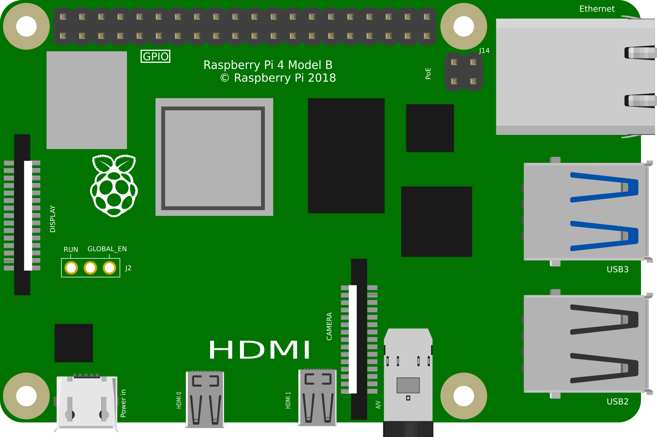

Image of Raspberry Pi 4B
Cirkit Designer LogoDesign with Raspberry Pi 4B in Cirkit Designer

Introduction

The Raspberry Pi 4B is a compact, affordable single-board computer designed for a wide range of applications. It features a powerful quad-core processor, up to 8GB of RAM, multiple USB ports, dual micro-HDMI outputs, and Ethernet connectivity. This versatile device is ideal for projects such as programming, media centers, IoT applications, robotics, and more. Its small form factor and robust capabilities make it a popular choice for both hobbyists and professionals.

Explore Projects Built with Raspberry Pi 4B
Use Cirkit Designer to design, explore, and prototype these projects online. Some projects support real-time simulation. Click "Open Project" to start designing instantly!
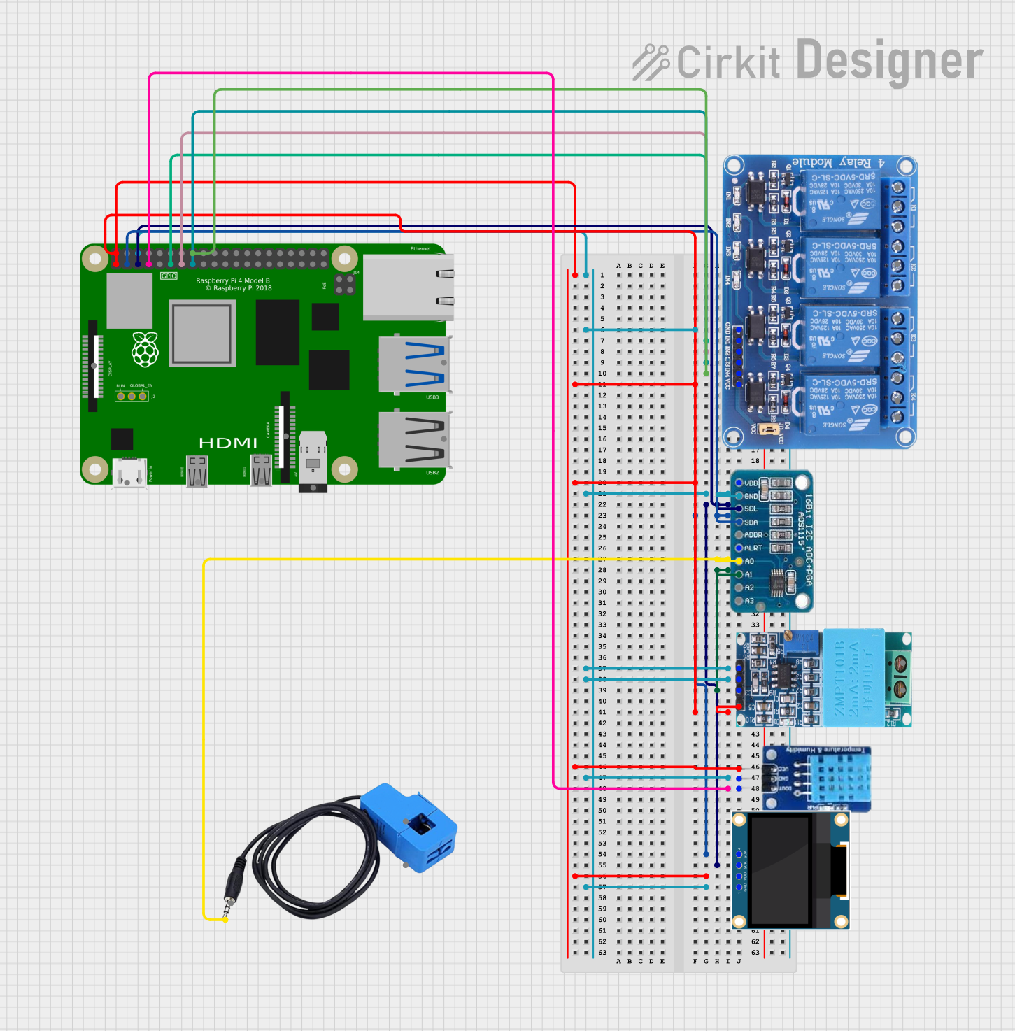
Raspberry Pi 4B-Controlled Relay System with Environmental Sensing and Power Monitoring
Image of smart_power_meter: A project utilizing Raspberry Pi 4B in a practical application
This circuit is designed to interface a Raspberry Pi 4B with various sensors and output devices. It includes a 4-channel relay for controlling external loads, an ADS1115 for analog-to-digital conversion of signals from a current sensor and a ZMPT101B voltage sensor, a DHT11 for temperature and humidity readings, and a 0.96" OLED display for data output. The Raspberry Pi 4B serves as the central controller, managing data acquisition from the sensors, processing the information, and driving the relay and display based on the sensor inputs and programmed logic.
Cirkit Designer LogoOpen Project in Cirkit Designer
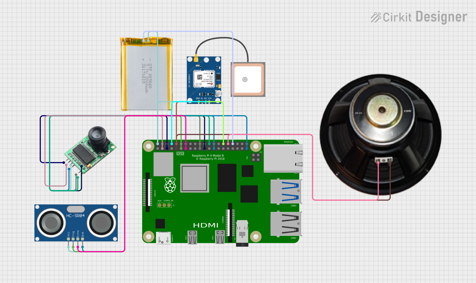
Raspberry Pi 4B-Based Smart Surveillance System with GPS and Ultrasonic Sensing
Image of VisionTool: A project utilizing Raspberry Pi 4B in a practical application
This circuit features a Raspberry Pi 4B as the central processing unit, interfacing with an Arducam camera module, an HC-SR04 ultrasonic sensor, a GPS NEO 6M module, and a speaker. The Raspberry Pi manages image capture, distance measurement, GPS data reception, and audio output. Power is supplied to the components from a 2000mAh battery, and the Raspberry Pi facilitates communication and control over the I2C, GPIO, and serial interfaces.
Cirkit Designer LogoOpen Project in Cirkit Designer
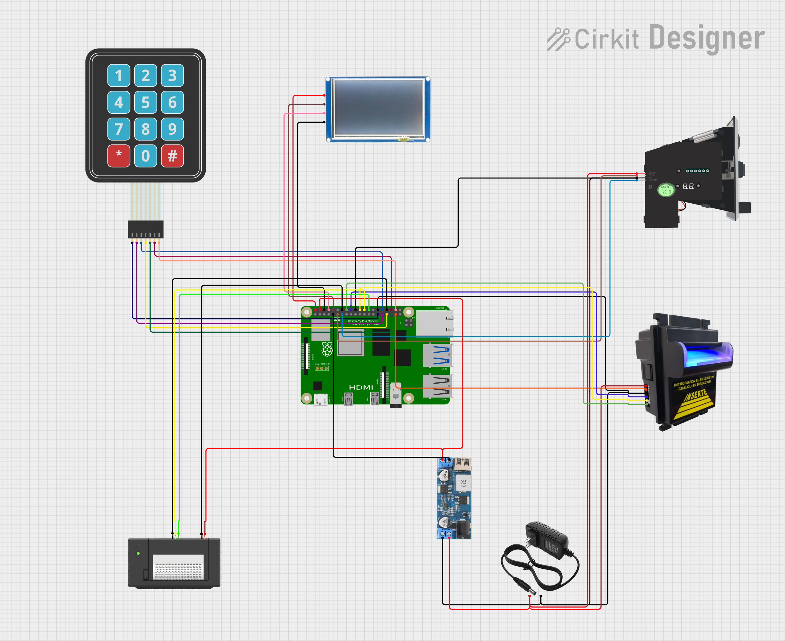
Raspberry Pi 4B-based Payment Kiosk with Coin and Bill Acceptors
Image of Scheme thesis: A project utilizing Raspberry Pi 4B in a practical application
This circuit features a Raspberry Pi 4B as the central controller, interfaced with a variety of peripherals for a payment and display system. It includes a bill acceptor and multi coin acceptor for monetary input, a thermal printer for receipts, and a touch display for user interaction. The circuit also incorporates a 12V to 5V step-down converter to power the 5V components and a membrane matrix keypad for additional input options.
Cirkit Designer LogoOpen Project in Cirkit Designer
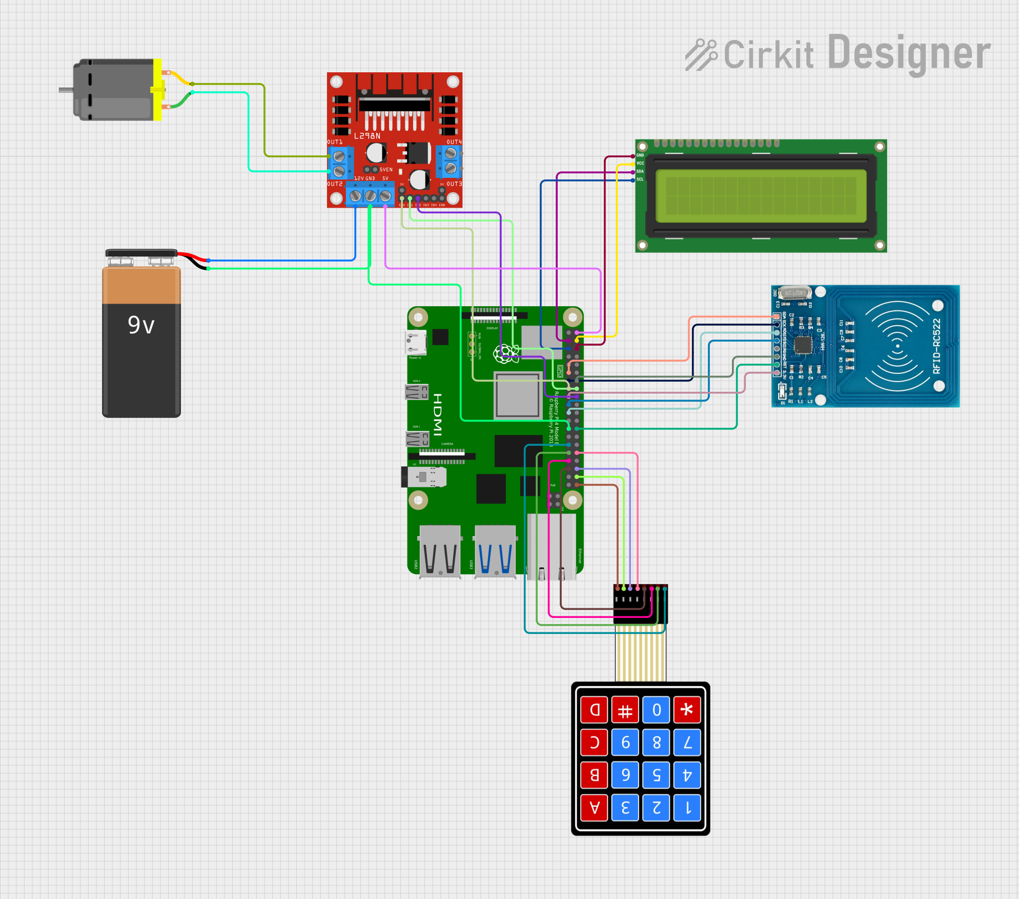
Raspberry Pi 4B Controlled RFID and Keypad Security System with I2C LCD Feedback and Motorized Lock Mechanism
Image of CVM: A project utilizing Raspberry Pi 4B in a practical application
This circuit features a Raspberry Pi 4B as the central controller, interfaced with an I2C LCD screen for display, an RFID-RC522 module for RFID reading, a 4x4 membrane matrix keypad for user input, and an L298N motor driver to control a DC motor. The Raspberry Pi manages data communication with the LCD via I2C, reads RFID tags, processes keypad inputs, and controls the motor's operation. Power is supplied to the motor driver and the Raspberry Pi through a 9V battery and regulated 5V connections.
Cirkit Designer LogoOpen Project in Cirkit Designer

Explore Projects Built with Raspberry Pi 4B

Use Cirkit Designer to design, explore, and prototype these projects online. Some projects support real-time simulation. Click "Open Project" to start designing instantly!
Image of smart_power_meter: A project utilizing Raspberry Pi 4B in a practical application
Raspberry Pi 4B-Controlled Relay System with Environmental Sensing and Power Monitoring
This circuit is designed to interface a Raspberry Pi 4B with various sensors and output devices. It includes a 4-channel relay for controlling external loads, an ADS1115 for analog-to-digital conversion of signals from a current sensor and a ZMPT101B voltage sensor, a DHT11 for temperature and humidity readings, and a 0.96" OLED display for data output. The Raspberry Pi 4B serves as the central controller, managing data acquisition from the sensors, processing the information, and driving the relay and display based on the sensor inputs and programmed logic.
Cirkit Designer LogoOpen Project in Cirkit Designer
Image of VisionTool: A project utilizing Raspberry Pi 4B in a practical application
Raspberry Pi 4B-Based Smart Surveillance System with GPS and Ultrasonic Sensing
This circuit features a Raspberry Pi 4B as the central processing unit, interfacing with an Arducam camera module, an HC-SR04 ultrasonic sensor, a GPS NEO 6M module, and a speaker. The Raspberry Pi manages image capture, distance measurement, GPS data reception, and audio output. Power is supplied to the components from a 2000mAh battery, and the Raspberry Pi facilitates communication and control over the I2C, GPIO, and serial interfaces.
Cirkit Designer LogoOpen Project in Cirkit Designer
Image of Scheme thesis: A project utilizing Raspberry Pi 4B in a practical application
Raspberry Pi 4B-based Payment Kiosk with Coin and Bill Acceptors
This circuit features a Raspberry Pi 4B as the central controller, interfaced with a variety of peripherals for a payment and display system. It includes a bill acceptor and multi coin acceptor for monetary input, a thermal printer for receipts, and a touch display for user interaction. The circuit also incorporates a 12V to 5V step-down converter to power the 5V components and a membrane matrix keypad for additional input options.
Cirkit Designer LogoOpen Project in Cirkit Designer
Image of CVM: A project utilizing Raspberry Pi 4B in a practical application
Raspberry Pi 4B Controlled RFID and Keypad Security System with I2C LCD Feedback and Motorized Lock Mechanism
This circuit features a Raspberry Pi 4B as the central controller, interfaced with an I2C LCD screen for display, an RFID-RC522 module for RFID reading, a 4x4 membrane matrix keypad for user input, and an L298N motor driver to control a DC motor. The Raspberry Pi manages data communication with the LCD via I2C, reads RFID tags, processes keypad inputs, and controls the motor's operation. Power is supplied to the motor driver and the Raspberry Pi through a 9V battery and regulated 5V connections.
Cirkit Designer LogoOpen Project in Cirkit Designer

Common Applications and Use Cases

  • Programming and Education: Ideal for learning programming languages like Python, C++, and Java.
  • Media Centers: Can be used to build a home theater system with software like Kodi.
  • IoT Projects: Acts as a hub for Internet of Things devices and sensors.
  • Robotics: Powers robots with its GPIO pins and processing capabilities.
  • Web Servers: Functions as a lightweight web server for hosting small websites or applications.
  • AI and Machine Learning: Supports AI/ML projects with frameworks like TensorFlow Lite.

Technical Specifications

Key Technical Details

Specification Details
Processor Quad-core Cortex-A72 (ARM v8) 64-bit SoC @ 1.5GHz
RAM Options 2GB, 4GB, or 8GB LPDDR4
USB Ports 2 × USB 3.0, 2 × USB 2.0
Video Output 2 × micro-HDMI ports (up to 4K resolution)
Networking Gigabit Ethernet, 802.11ac Wi-Fi, Bluetooth 5.0
GPIO Pins 40-pin GPIO header
Storage MicroSD card slot, USB boot support
Power Supply 5V/3A via USB-C
Dimensions 85.6mm × 56.5mm × 17mm
Operating System Support Raspberry Pi OS (formerly Raspbian), Ubuntu, and other Linux distros

Pin Configuration and Descriptions

The Raspberry Pi 4B features a 40-pin GPIO header for interfacing with external components. Below is a summary of the pin configuration:

Pin Number Pin Name Description
1 3.3V Power 3.3V power supply
2 5V Power 5V power supply
3 GPIO2 (SDA1) I2C Data
4 5V Power 5V power supply
5 GPIO3 (SCL1) I2C Clock
6 Ground Ground
7 GPIO4 General-purpose I/O
8 GPIO14 (TXD0) UART Transmit
9 Ground Ground
10 GPIO15 (RXD0) UART Receive
... ... ... (Refer to official GPIO pinout)

For the full GPIO pinout, refer to the official Raspberry Pi documentation.


Usage Instructions

How to Use the Raspberry Pi 4B in a Circuit

  1. Powering the Raspberry Pi: Use a 5V/3A USB-C power adapter to power the board.
  2. Connecting Peripherals: Attach a keyboard, mouse, and monitor via USB and HDMI ports.
  3. Installing the Operating System:
    • Download the Raspberry Pi Imager tool from the official website.
    • Flash the desired OS (e.g., Raspberry Pi OS) onto a microSD card.
    • Insert the microSD card into the Raspberry Pi's card slot.
  4. Booting Up: Power on the Raspberry Pi and follow the on-screen setup instructions.
  5. Using GPIO Pins: Connect external components (e.g., LEDs, sensors) to the GPIO pins. Use Python libraries like RPi.GPIO or gpiozero to control the pins.

Important Considerations and Best Practices

  • Cooling: Use a heatsink or fan for cooling, especially for intensive tasks.
  • Power Supply: Ensure the power adapter provides sufficient current (5V/3A) to avoid instability.
  • Static Protection: Handle the board carefully to avoid static discharge damage.
  • GPIO Safety: Avoid exceeding the 3.3V limit on GPIO pins to prevent damage.

Example: Blinking an LED with GPIO

Below is an example of how to blink an LED connected to GPIO pin 17 using Python:

import RPi.GPIO as GPIO  # Import the GPIO library
import time              # Import the time library for delays

Pin configuration

LED_PIN = 17 # GPIO pin where the LED is connected

GPIO setup

GPIO.setmode(GPIO.BCM) # Use Broadcom pin numbering GPIO.setup(LED_PIN, GPIO.OUT) # Set the LED pin as an output

try: while True: GPIO.output(LED_PIN, GPIO.HIGH) # Turn the LED on time.sleep(1) # Wait for 1 second GPIO.output(LED_PIN, GPIO.LOW) # Turn the LED off time.sleep(1) # Wait for 1 second except KeyboardInterrupt: # Clean up GPIO settings on exit GPIO.cleanup()


---

Troubleshooting and FAQs

Common Issues and Solutions

  1. The Raspberry Pi does not boot:

    • Ensure the microSD card is properly inserted and contains a valid OS image.
    • Verify the power supply provides 5V/3A.
    • Check for any visible damage to the board.
  2. Wi-Fi connectivity issues:

    • Ensure the correct Wi-Fi credentials are entered.
    • Check if the Wi-Fi network is within range.
    • Update the OS to the latest version for improved driver support.
  3. Overheating:

    • Use a heatsink or fan to improve cooling.
    • Avoid placing the Raspberry Pi in an enclosed space without ventilation.
  4. GPIO pins not working:

    • Double-check the pin connections and ensure the correct pin numbering is used in the code.
    • Verify that the GPIO pins are not damaged or shorted.

FAQs

  • Can I power the Raspberry Pi 4B via USB ports? No, the Raspberry Pi 4B must be powered via the USB-C power input.

  • What is the maximum resolution supported by the Raspberry Pi 4B? The Raspberry Pi 4B supports dual 4K displays via its micro-HDMI ports.

  • Can I use the Raspberry Pi 4B as a desktop computer? Yes, with a suitable OS like Raspberry Pi OS, the Raspberry Pi 4B can function as a basic desktop computer.

  • How do I enable SSH on the Raspberry Pi? Create an empty file named ssh (without any extension) in the boot partition of the microSD card before booting.


This concludes the documentation for the Raspberry Pi 4B. For further details, refer to the official Raspberry Pi website.