How to Use MIC2571: Examples, Pinouts, and Specs
Introduction
The MIC2571 is a high-efficiency step-up (boost) voltage regulator designed to convert a low-voltage input to a higher voltage output. This component is particularly useful in battery-powered applications where extending battery life is crucial. It is capable of delivering high output currents with high efficiency, making it suitable for portable devices, microcontroller power supplies, and other electronics requiring a stable, higher voltage supply.
Explore Projects Built with MIC2571


Explore Projects Built with MIC2571
Common Applications
- Portable electronic devices
- Battery-powered equipment
- Power supply for microcontrollers and digital ICs
- LED drivers
Technical Specifications
Key Technical Details
- Input Voltage Range: 0.8V to VOUT
- Output Voltage Range: 2.5V to 34V
- Maximum Output Current: Varies with input voltage and inductor choice
- Switching Frequency: 100kHz to 2MHz (adjustable)
- Quiescent Current: Typically 110µA
- Efficiency: Up to 90% (depending on input/output voltages and load)
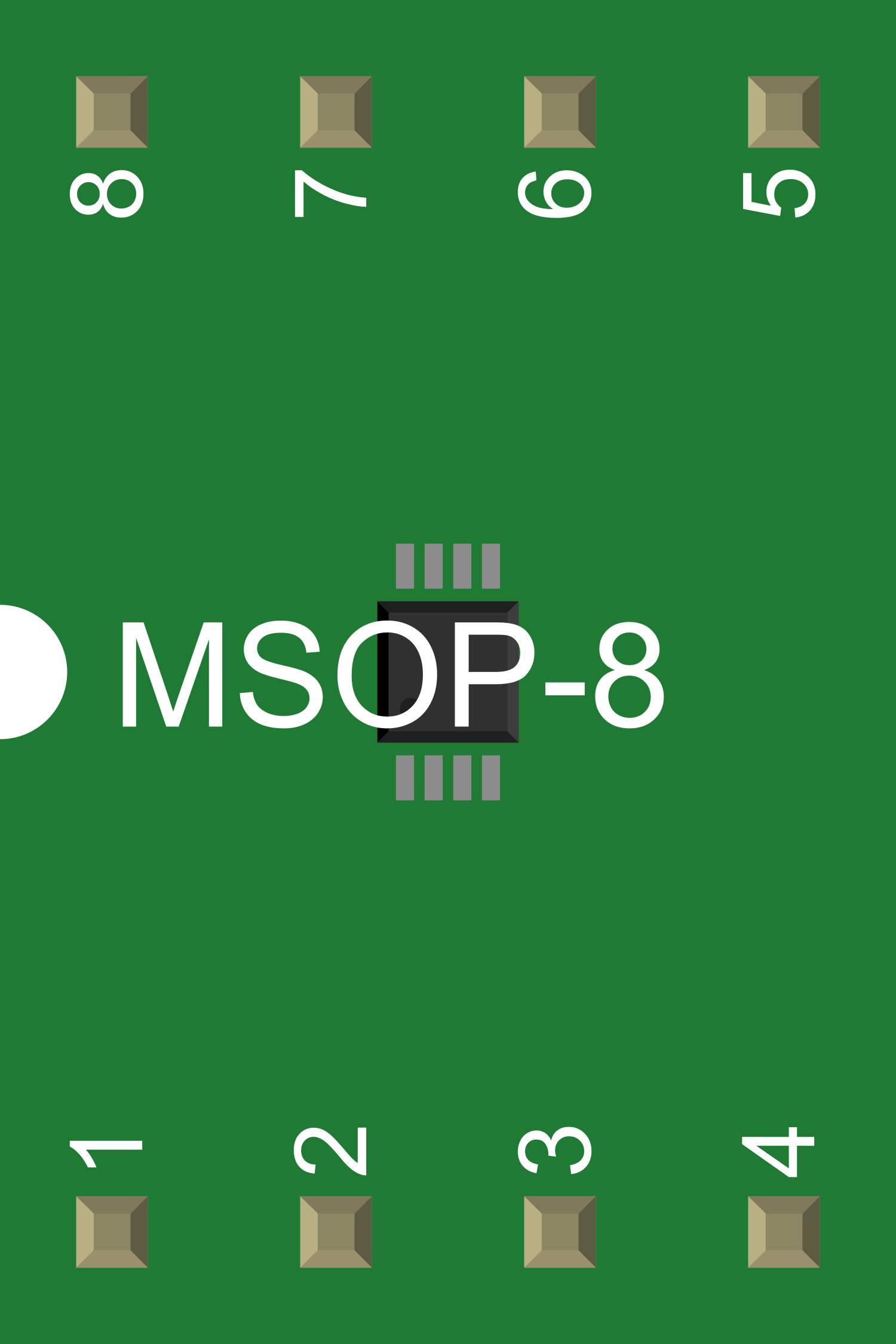
Pin Configuration and Descriptions
| Pin Number | Name | Description |
|---|---|---|
| 1 | LX | Inductor connection to internal switch |
| 2 | GND | Ground reference for the regulator |
| 3 | FB | Feedback voltage input |
| 4 | SHDN | Shutdown input (active low) |
| 5 | VIN | Input voltage supply |
| 6 | BYP | Bypass capacitor connection |
| 7 | EN | Enable input (active high) |
| 8 | FREQ | Frequency adjust input |
Usage Instructions
How to Use the MIC2571 in a Circuit
Input Supply Connection: Connect a voltage source to the VIN pin (5) and ground to the GND pin (2). Ensure the voltage source is within the specified input voltage range.
Output Voltage Setting: Connect a resistor divider from the output voltage to the FB pin (3) to set the desired output voltage. The voltage at FB should be 1.25V for proper regulation.
Inductor Selection: Choose an inductor with a current rating above the maximum output current and connect it to the LX pin (1).
Capacitor Selection: Connect a bypass capacitor between the BYP pin (6) and GND, and an output capacitor from the output voltage to GND to stabilize the output.
Frequency Adjustment: If necessary, adjust the switching frequency by connecting a resistor to the FREQ pin (8).
Shutdown Control: The SHDN pin (4) can be driven low to shut down the regulator. Connect this to a logic signal or leave it unconnected (pulled high internally) for normal operation.
Enable Control: The EN pin (7) can be used to enable the regulator when driven high. Connect this to a logic signal or tie it to VIN for automatic operation.
Important Considerations and Best Practices
- Ensure that all components are rated for the correct current and voltage levels.
- Place the input and output capacitors as close to the MIC2571 pins as possible to minimize noise and improve stability.
- Use a ground plane for better thermal performance and noise reduction.
- Avoid long trace lengths for the switch node (LX pin) to reduce EMI.
- If the regulator is used in a battery-powered application, consider the quiescent current to maximize battery life.
Troubleshooting and FAQs
Common Issues
- Output Voltage Not Regulated: Check the feedback resistor divider and ensure that the FB pin voltage is set correctly.
- Excessive Noise or Ripple: Verify the input and output capacitor values and ESR ratings. Increase capacitance or improve capacitor quality if necessary.
- Thermal Shutdown: Ensure adequate cooling and airflow around the component. Check if the inductor or input current is too high.
Solutions and Tips for Troubleshooting
- If the output voltage is incorrect, re-calculate the feedback resistor values and ensure proper soldering.
- For noise issues, add additional capacitors or use capacitors with lower ESR.
- In case of thermal issues, improve the PCB layout with better heat dissipation or reduce the load current.
FAQs
Q: Can the MIC2571 be used to power an Arduino UNO? A: Yes, the MIC2571 can be used to step up a lower voltage source to the 5V required by an Arduino UNO.
Q: What is the maximum output current of the MIC2571? A: The maximum output current depends on the input voltage, inductor choice, and thermal conditions. Refer to the datasheet for specific current ratings.
Q: How do I adjust the switching frequency? A: The switching frequency can be adjusted by connecting a resistor to the FREQ pin. Refer to the datasheet for the resistor value calculation.
Q: Is the MIC2571 suitable for driving LEDs? A: Yes, the MIC2571 can be used as a constant voltage source for driving LEDs, provided the output current does not exceed the maximum rating.
Example Arduino Connection Code
// Example code to control MIC2571 SHDN and EN pins using an Arduino UNO

const int shutdownPin = 2; // Connect to MIC2571 SHDN pin
const int enablePin = 3;   // Connect to MIC2571 EN pin

void setup() {
  pinMode(shutdownPin, OUTPUT);
  pinMode(enablePin, OUTPUT);

  // Start with the regulator enabled and not in shutdown
  digitalWrite(shutdownPin, HIGH);
  digitalWrite(enablePin, HIGH);
}

void loop() {
  // Example: Toggle the regulator on and off every 5 seconds
  digitalWrite(enablePin, LOW);  // Disable the regulator
  delay(5000);
  digitalWrite(enablePin, HIGH); // Enable the regulator
  delay(5000);
}
Note: This code is for illustrative purposes only. The actual implementation may vary based on the specific application and circuit design. Always refer to the MIC2571 datasheet for detailed information and consult the Arduino documentation for pin assignments and functions.