How to Use Wireless Power Supply Transmitter Charging Coil Module : Examples, Pinouts, and Specs
Introduction
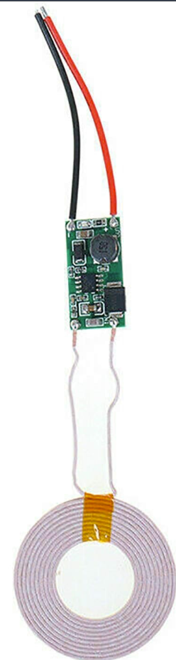
The Wireless Power Supply Transmitter Charging Coil Module is a device designed to wirelessly transmit power to compatible receivers using the principle of electromagnetic induction. This module is commonly used in applications where physical connectors are impractical or undesirable, such as in wireless charging systems for smartphones, electric toothbrushes, wearable devices, and other portable electronics. By eliminating the need for direct electrical contact, this module enhances durability, convenience, and safety in power transfer systems.
Explore Projects Built with Wireless Power Supply Transmitter Charging Coil Module

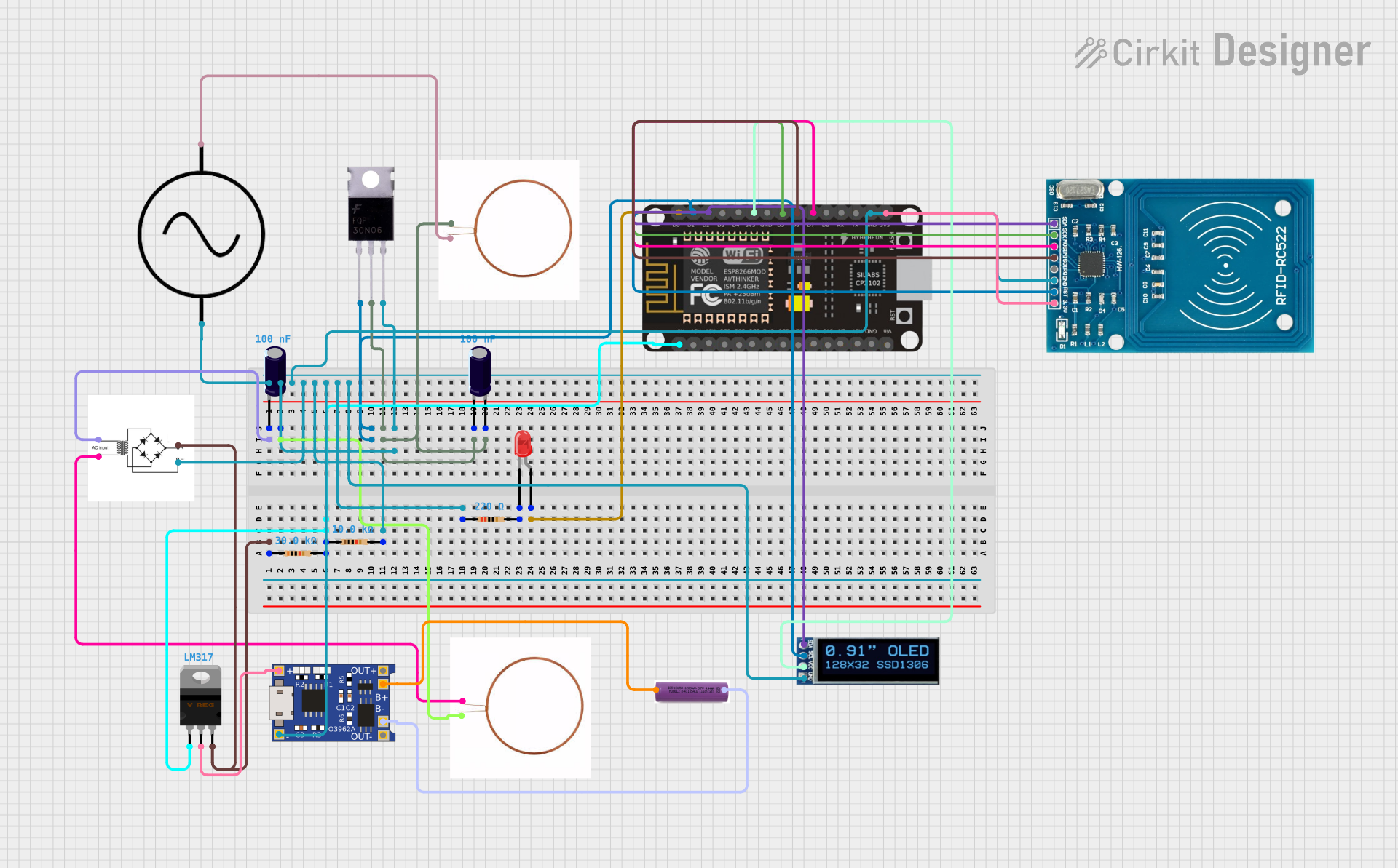
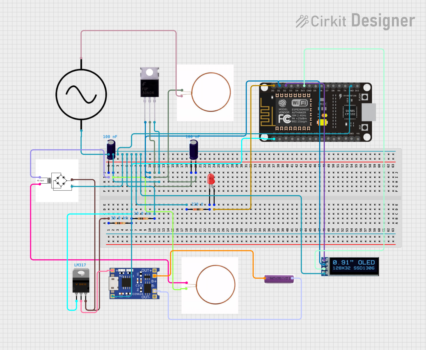

Explore Projects Built with Wireless Power Supply Transmitter Charging Coil Module
Technical Specifications
Below are the key technical details and pin configuration for the Wireless Power Supply Transmitter Charging Coil Module:
Key Technical Details
| Parameter | Value |
|---|---|
| Input Voltage | 5V DC |
| Input Current | 1A (typical) |
| Output Power | Up to 5W |
| Transmission Distance | 2-10 mm (optimal range) |
| Operating Frequency | 100-200 kHz |
| Efficiency | ~70% (depending on alignment) |
| Coil Diameter | 43 mm (typical) |
| Operating Temperature | -10°C to 50°C |
Pin Configuration and Descriptions
| Pin Name | Description |
|---|---|
| VCC | Positive power supply input (5V DC) |
| GND | Ground connection |
| TX Coil+ | Positive terminal of the transmitter coil |
| TX Coil- | Negative terminal of the transmitter coil |
Usage Instructions
How to Use the Component in a Circuit
- Power Supply: Connect the
VCCpin to a stable 5V DC power source and theGNDpin to ground. Ensure the power supply can provide at least 1A of current. - Coil Connection: Attach the transmitter coil to the
TX Coil+andTX Coil-pins. Ensure proper polarity and secure connections. - Receiver Alignment: Place the compatible receiver coil within the transmission distance (2-10 mm) for optimal power transfer. Ensure the coils are aligned for maximum efficiency.
- Load Connection: The receiver module should be connected to the load (e.g., a battery or device) to complete the wireless charging system.
Important Considerations and Best Practices
- Alignment: Proper alignment between the transmitter and receiver coils is critical for efficient power transfer. Misalignment can reduce efficiency or prevent charging altogether.
- Distance: Keep the transmission distance within the specified range (2-10 mm). Excessive distance will result in power loss or failure to transmit power.
- Heat Management: Ensure adequate ventilation around the module to prevent overheating during operation.
- Interference: Avoid placing the module near metal objects or other electronic devices that may interfere with the electromagnetic field.
- Safety: Do not exceed the input voltage or current ratings to prevent damage to the module.
Example: Using with an Arduino UNO
While the Wireless Power Supply Transmitter Charging Coil Module does not directly interface with an Arduino, you can use an Arduino to monitor or control the power supply. Below is an example of how to monitor the input voltage using an Arduino UNO:
// Define the analog pin connected to the voltage divider
const int voltagePin = A0;

// Define the reference voltage of the Arduino (5V for most boards)
const float referenceVoltage = 5.0;

// Define the voltage divider ratio (adjust based on your circuit)
const float dividerRatio = 2.0;

void setup() {
  Serial.begin(9600); // Initialize serial communication at 9600 baud
  pinMode(voltagePin, INPUT); // Set the voltage pin as input
}

void loop() {
  int sensorValue = analogRead(voltagePin); // Read the analog value
  // Calculate the input voltage using the reference voltage and divider ratio
  float inputVoltage = (sensorValue / 1023.0) * referenceVoltage * dividerRatio;

  // Print the input voltage to the Serial Monitor
  Serial.print("Input Voltage: ");
  Serial.print(inputVoltage);
  Serial.println(" V");

  delay(1000); // Wait for 1 second before the next reading
}
Note: Use a voltage divider circuit to step down the input voltage to a safe level for the Arduino's analog pin (0-5V).
Troubleshooting and FAQs
Common Issues and Solutions
No Power Transmission
- Cause: Misalignment between the transmitter and receiver coils.
- Solution: Adjust the position of the receiver coil to ensure proper alignment.
Overheating
- Cause: Prolonged operation at high current or poor ventilation.
- Solution: Ensure adequate airflow around the module and avoid exceeding the rated input current.
Low Efficiency
- Cause: Excessive transmission distance or interference from nearby objects.
- Solution: Reduce the distance between the coils and remove any metallic objects near the module.
No Output on Receiver Side
- Cause: Faulty connection or damaged receiver module.
- Solution: Check all connections and test the receiver module with a multimeter.
FAQs
Q1: Can this module charge any device wirelessly?
A1: No, the device must have a compatible receiver module designed for wireless charging.
Q2: What happens if the input voltage exceeds 5V?
A2: Exceeding the input voltage may damage the module. Always use a regulated 5V power supply.
Q3: Can I increase the transmission distance?
A3: The transmission distance is limited by the design of the module and the coils. Increasing the distance may significantly reduce efficiency or prevent power transfer.
Q4: Is this module compatible with Qi wireless charging standards?
A4: This module is not guaranteed to be Qi-certified. Check the specifications of your receiver module for compatibility.
By following this documentation, you can effectively integrate the Wireless Power Supply Transmitter Charging Coil Module into your projects and troubleshoot common issues.