How to Use RGB Light (Common Cathode): Examples, Pinouts, and Specs

Introduction
An RGB light with a common cathode configuration is a versatile electronic component that combines three LEDs (red, green, and blue) into a single package. The cathode (negative terminal) is shared among all three LEDs and is connected to ground, while the anodes (positive terminals) for each color are controlled separately. By adjusting the intensity of each LED, you can create a wide spectrum of colors, making this component ideal for applications requiring dynamic lighting effects.
Explore Projects Built with RGB Light (Common Cathode)

Explore Projects Built with RGB Light (Common Cathode)
Common Applications and Use Cases
- Decorative lighting and ambient color effects
- Status indicators in electronic devices
- DIY projects and prototyping
- RGB displays and signage
- Educational projects to demonstrate color mixing principles
Technical Specifications
Below are the key technical details for a typical RGB light (common cathode):
| Parameter | Value |
|---|---|
| Forward Voltage (Red) | 1.8V - 2.2V |
| Forward Voltage (Green) | 3.0V - 3.4V |
| Forward Voltage (Blue) | 3.0V - 3.4V |
| Forward Current (per LED) | 20mA (typical) |
| Maximum Current (per LED) | 30mA |
| Common Cathode Pin | Connected to ground (GND) |
| Package Type | 4-pin through-hole or SMD |
Pin Configuration and Descriptions
The RGB light (common cathode) typically has four pins. The table below describes each pin:
| Pin Number | Name | Description |
|---|---|---|
| 1 | Red Anode | Positive terminal for the red LED |
| 2 | Common Cathode | Shared negative terminal for all LEDs (connect to GND) |
| 3 | Green Anode | Positive terminal for the green LED |
| 4 | Blue Anode | Positive terminal for the blue LED |
Usage Instructions
How to Use the Component in a Circuit
- Connect the Common Cathode: Connect the cathode pin (Pin 2) to the ground (GND) of your circuit.
- Control the Anodes: Connect the red, green, and blue anodes (Pins 1, 3, and 4) to a current-limiting resistor (typically 220Ω to 330Ω) and then to a voltage source or microcontroller pins.
- Adjust Intensity: Use Pulse Width Modulation (PWM) signals from a microcontroller (e.g., Arduino UNO) to control the brightness of each LED and mix colors.
Important Considerations and Best Practices
- Use Resistors: Always use appropriate current-limiting resistors to prevent damage to the LEDs.
- Voltage Levels: Ensure the voltage supplied to each anode matches the forward voltage of the respective LED.
- Heat Management: Avoid exceeding the maximum current rating to prevent overheating.
- PWM Control: For smooth color transitions, use PWM signals to vary the intensity of each LED.
Example: Connecting to an Arduino UNO
Below is an example of how to connect and control an RGB light (common cathode) using an Arduino UNO:
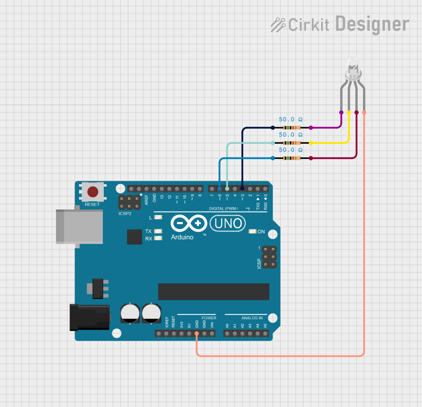
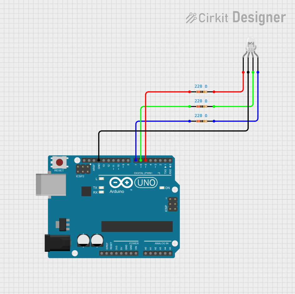
Circuit Diagram
- Connect the cathode pin to the GND pin of the Arduino.
- Connect the red, green, and blue anodes to Arduino digital pins (e.g., D9, D10, D11) through 220Ω resistors.
Arduino Code
// Define the pins for the RGB anodes
const int redPin = 9;   // Red anode connected to pin D9
const int greenPin = 10; // Green anode connected to pin D10
const int bluePin = 11;  // Blue anode connected to pin D11

void setup() {
  // Set the RGB pins as output
  pinMode(redPin, OUTPUT);
  pinMode(greenPin, OUTPUT);
  pinMode(bluePin, OUTPUT);
}

void loop() {
  // Example: Display purple color by mixing red and blue
  analogWrite(redPin, 128);  // Set red intensity (0-255)
  analogWrite(greenPin, 0);  // Turn off green
  analogWrite(bluePin, 128); // Set blue intensity (0-255)
  delay(1000);               // Wait for 1 second

  // Example: Display cyan color by mixing green and blue
  analogWrite(redPin, 0);    // Turn off red
  analogWrite(greenPin, 128);// Set green intensity (0-255)
  analogWrite(bluePin, 128); // Set blue intensity (0-255)
  delay(1000);               // Wait for 1 second

  // Example: Display white color by mixing all three LEDs
  analogWrite(redPin, 128);  // Set red intensity (0-255)
  analogWrite(greenPin, 128);// Set green intensity (0-255)
  analogWrite(bluePin, 128); // Set blue intensity (0-255)
  delay(1000);               // Wait for 1 second
}
Troubleshooting and FAQs
Common Issues and Solutions
LEDs Not Lighting Up
- Cause: Incorrect wiring or missing ground connection.
- Solution: Double-check the connections, ensuring the cathode is connected to GND and the anodes are connected through resistors.
Incorrect Colors Displayed
- Cause: Pins connected to the wrong anodes.
- Solution: Verify the pin configuration and ensure each anode is connected to the correct microcontroller pin.
LEDs Too Dim
- Cause: Resistor value too high.
- Solution: Use a lower resistor value (e.g., 220Ω) to increase brightness, but do not exceed the current rating.
Overheating
- Cause: Exceeding the maximum current rating.
- Solution: Use appropriate resistors and avoid driving the LEDs at maximum current for extended periods.
FAQs
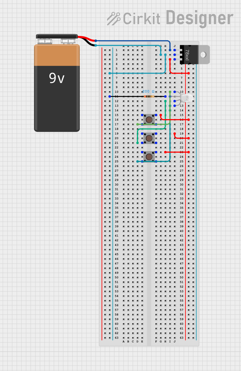
Q: Can I use the RGB light without a microcontroller?
A: Yes, you can use switches or potentiometers to manually control the anodes and adjust the colors.Q: What happens if I connect the cathode to a positive voltage?
A: The LEDs will not light up, as the common cathode must be connected to ground for proper operation.Q: Can I use the RGB light with a 3.3V microcontroller?
A: Yes, but ensure the forward voltage of each LED is compatible with the 3.3V supply and adjust resistor values accordingly.