How to Use buck: Examples, Pinouts, and Specs
Introduction
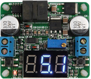
A buck converter, also known as a step-down converter, is a type of DC-DC converter that efficiently reduces a higher input voltage to a lower output voltage while increasing the current. It is widely used in power supply systems due to its high efficiency and compact design. The buck converter operates using a combination of switching elements (such as MOSFETs) and energy storage components (inductors and capacitors) to regulate the output voltage.
Explore Projects Built with buck


Explore Projects Built with buck
Common Applications and Use Cases
- Powering low-voltage devices from higher-voltage sources (e.g., 12V to 5V conversion)
- Battery-powered systems to extend battery life
- Voltage regulation in embedded systems
- LED drivers and motor controllers
- Renewable energy systems (e.g., solar power systems)
Technical Specifications
Below are the general technical specifications for a typical buck converter. Specific values may vary depending on the manufacturer and model.
| Parameter | Value |
|---|---|
| Input Voltage Range | 4.5V to 40V |
| Output Voltage Range | 0.8V to 36V |
| Output Current | Up to 10A (depending on design) |
| Efficiency | Up to 95% |
| Switching Frequency | 100 kHz to 1 MHz |
| Operating Temperature | -40°C to +125°C |
Pin Configuration and Descriptions
The pinout of a buck converter IC may vary depending on the specific model. Below is an example of a common pin configuration:
| Pin Name | Description |
|---|---|
| VIN | Input voltage pin. Connect to the higher voltage source. |
| VOUT | Output voltage pin. Provides the regulated lower voltage. |
| GND | Ground pin. Connect to the system ground. |
| EN | Enable pin. Used to turn the converter on or off. |
| FB | Feedback pin. Used to regulate the output voltage by connecting to a resistor divider. |
| SW | Switch pin. Connects to the inductor and controls the switching operation. |
| COMP | Compensation pin. Used for stability and loop compensation. |
Usage Instructions
How to Use the Buck Converter in a Circuit
- Input Voltage Selection: Ensure the input voltage (VIN) is within the specified range of the buck converter.
- Output Voltage Configuration: Use a resistor divider network connected to the feedback (FB) pin to set the desired output voltage (VOUT). Refer to the formula in the datasheet for precise calculations.
- Inductor and Capacitor Selection: Choose an appropriate inductor and output capacitor based on the desired output current and ripple requirements. The datasheet typically provides recommended values.
- Enable Pin: Connect the EN pin to VIN or a control signal to enable the converter.
- Switching Node: Connect the SW pin to the inductor and ensure proper PCB layout to minimize noise.
- Grounding: Connect all ground pins to a common ground plane to ensure stable operation.
Important Considerations and Best Practices
- Thermal Management: Ensure adequate heat dissipation, especially for high-current applications. Use heat sinks or thermal vias if necessary.
- PCB Layout: Minimize the loop area of the input capacitor, inductor, and output capacitor to reduce electromagnetic interference (EMI).
- Input and Output Capacitors: Use low-ESR capacitors to minimize voltage ripple.
- Startup Behavior: Check the soft-start feature (if available) to prevent inrush current during power-up.
- Protection Features: Verify the presence of overcurrent, overvoltage, and thermal protection features for safe operation.
Example: Using a Buck Converter with Arduino UNO
Below is an example of how to use a buck converter to power an Arduino UNO from a 12V source:
- Connect the 12V input to the VIN pin of the buck converter.
- Set the output voltage to 5V using the feedback resistor divider.
- Connect the 5V output of the buck converter to the Arduino UNO's 5V pin.
- Connect the ground of the buck converter to the Arduino UNO's GND pin.
// Example Arduino code to blink an LED powered by a buck converter
// Ensure the buck converter is set to output 5V for the Arduino UNO

const int ledPin = 13; // Pin connected to the onboard LED

void setup() {
  pinMode(ledPin, OUTPUT); // Set the LED pin as an output
}

void loop() {
  digitalWrite(ledPin, HIGH); // Turn the LED on
  delay(1000);                // Wait for 1 second
  digitalWrite(ledPin, LOW);  // Turn the LED off
  delay(1000);                // Wait for 1 second
}
Troubleshooting and FAQs
Common Issues and Solutions
No Output Voltage:
- Check if the EN pin is properly connected to enable the converter.
- Verify the input voltage is within the specified range.
- Inspect the feedback resistor network for proper configuration.
Excessive Output Ripple:
- Use low-ESR capacitors for input and output filtering.
- Ensure the inductor value is appropriate for the load current.
Overheating:
- Check for proper heat dissipation and ensure the load current is within the rated limit.
- Verify the PCB layout minimizes thermal resistance.
Noise or EMI Issues:
- Minimize the loop area of high-current paths.
- Use proper grounding techniques and shielding if necessary.
FAQs
Q: Can I use a buck converter to power sensitive analog circuits?
A: Yes, but ensure the output voltage ripple is minimized by using low-ESR capacitors and proper filtering techniques.
Q: What happens if the input voltage drops below the specified range?
A: The buck converter may stop regulating the output voltage, leading to instability or a complete shutdown.
Q: Can I use a buck converter for bidirectional power flow?
A: No, a standard buck converter is designed for unidirectional power flow. For bidirectional applications, consider using a buck-boost converter.
Q: How do I calculate the feedback resistor values?
A: Refer to the formula in the datasheet:
( V_{OUT} = V_{REF} \times \left(1 + \frac{R_1}{R_2}\right) ),
where ( V_{REF} ) is the reference voltage of the feedback pin.
By following this documentation, users can effectively integrate a buck converter into their projects for efficient voltage regulation.