How to Use Contactor & Overload: Examples, Pinouts, and Specs
Introduction
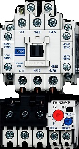
A Contactor & Overload is an essential electromechanical device used in electrical circuits to control the flow of power to motors, lighting systems, and other high-power loads. The contactor acts as a switch that can be controlled remotely, while the overload relay protects the connected equipment from damage caused by excessive current or overheating.
These components are widely used in industrial automation, motor control centers, HVAC systems, and other applications requiring reliable switching and protection for electrical loads.
Explore Projects Built with Contactor & Overload


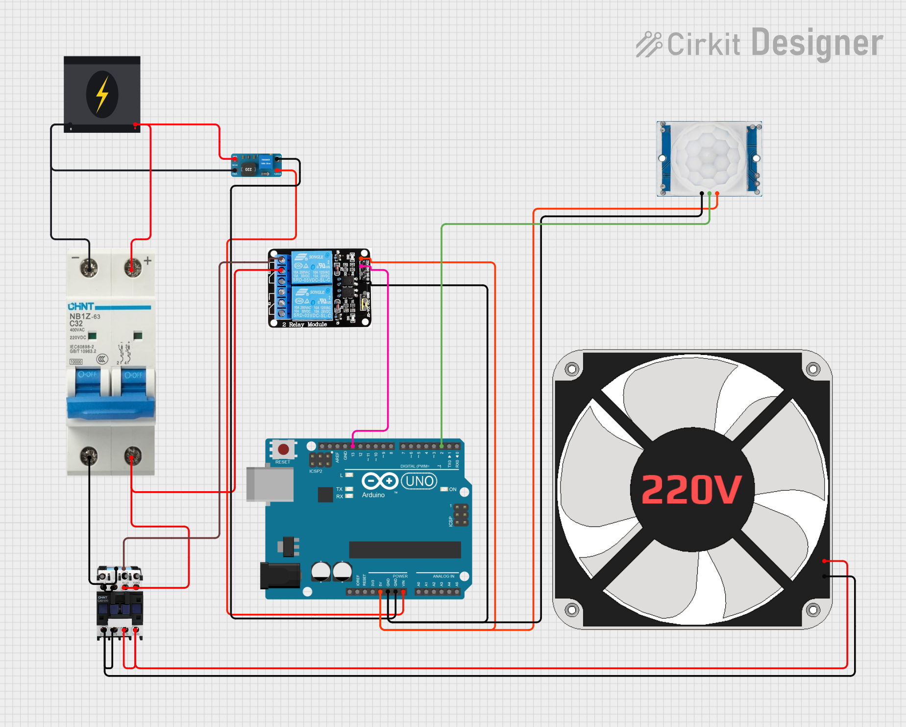
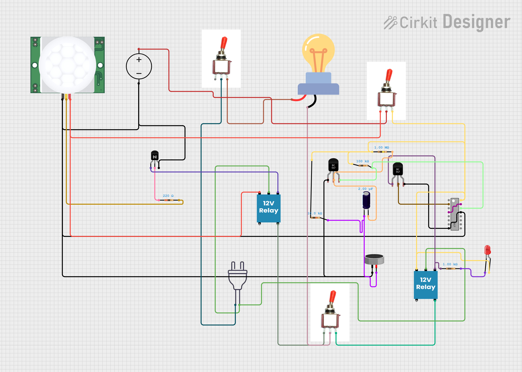
Explore Projects Built with Contactor & Overload
Technical Specifications
Contactor Specifications
| Parameter | Value |
|---|---|
| Manufacturer | 230V |
| Rated Operating Voltage | 230V AC |
| Rated Current | 9A, 12A, 18A (varies by model) |
| Coil Voltage | 230V AC |
| Number of Poles | 3P (Three Poles) |
| Mechanical Life | 10 million operations |
| Electrical Life | 1 million operations |
| Mounting Type | DIN Rail or Panel Mount |
Overload Relay Specifications
| Parameter | Value |
|---|---|
| Manufacturer | 230V |
| Current Range | 0.1A to 32A (adjustable) |
| Trip Class | Class 10 |
| Reset Type | Manual/Automatic |
| Contact Configuration | 1 NO + 1 NC |
| Mounting Type | Direct mount on contactor |
| Ambient Temperature | -20°C to +60°C |
Pin Configuration and Descriptions
Contactor
| Pin Label | Description |
|---|---|
| A1, A2 | Coil terminals for control voltage |
| L1, L2, L3 | Input terminals for power supply |
| T1, T2, T3 | Output terminals to the load |
| NO | Normally Open auxiliary contact |
| NC | Normally Closed auxiliary contact |
Overload Relay
| Pin Label | Description |
|---|---|
| L1, L2, L3 | Input terminals for power supply |
| T1, T2, T3 | Output terminals to the load |
| 95, 96 | Normally Closed (NC) trip contact |
| 97, 98 | Normally Open (NO) trip contact |
Usage Instructions
How to Use the Component in a Circuit
Wiring the Contactor:
- Connect the power supply lines to the input terminals (L1, L2, L3) of the contactor.
- Connect the load (e.g., motor) to the output terminals (T1, T2, T3).
- Wire the control circuit to the coil terminals (A1, A2) using a 230V AC control voltage.
Installing the Overload Relay:
- Mount the overload relay directly onto the contactor.
- Connect the input terminals (L1, L2, L3) of the overload relay to the output terminals of the contactor.
- Connect the load to the output terminals (T1, T2, T3) of the overload relay.
- Adjust the current setting on the overload relay to match the rated current of the load.
Control Circuit:
- Use a push-button switch or a programmable logic controller (PLC) to control the contactor coil.
- Auxiliary contacts (NO/NC) can be used for feedback or interlocking purposes.
Important Considerations and Best Practices
- Ensure the contactor and overload relay are rated for the voltage and current of your application.
- Always adjust the overload relay to the correct current setting to prevent nuisance tripping or insufficient protection.
- Use proper wire sizes and secure connections to avoid overheating or loose contacts.
- Verify that the control voltage matches the coil voltage of the contactor (230V AC in this case).
- Regularly inspect the contactor and overload relay for signs of wear or damage.
Arduino UNO Example Code
While contactors and overload relays are typically controlled by industrial control systems, you can use an Arduino UNO to control a contactor for demonstration purposes. Below is an example code to control a contactor using a relay module connected to the Arduino:
// Arduino code to control a contactor using a relay module
// Connect the relay module's IN pin to Arduino pin 7
// Ensure the relay module is rated for 230V AC switching

const int relayPin = 7; // Pin connected to the relay module

void setup() {
  pinMode(relayPin, OUTPUT); // Set relay pin as output
  digitalWrite(relayPin, LOW); // Ensure relay is off at startup
}

void loop() {
  // Turn the contactor ON
  digitalWrite(relayPin, HIGH); // Activate relay
  delay(5000); // Keep contactor ON for 5 seconds

  // Turn the contactor OFF
  digitalWrite(relayPin, LOW); // Deactivate relay
  delay(5000); // Keep contactor OFF for 5 seconds
}
Troubleshooting and FAQs
Common Issues Users Might Face
Contactor Not Switching:
- Cause: Incorrect control voltage or loose coil connections.
- Solution: Verify the control voltage (230V AC) and check the coil terminals (A1, A2).
Overload Relay Tripping Frequently:
- Cause: Incorrect current setting or overloaded motor.
- Solution: Adjust the overload relay to the correct current setting and ensure the load is within the rated capacity.
Excessive Heating of Contacts:
- Cause: Loose connections or undersized wires.
- Solution: Tighten all connections and use wires of appropriate gauge.
No Output from Overload Relay:
- Cause: Overload relay has tripped.
- Solution: Reset the relay manually or wait for automatic reset (if enabled).
Solutions and Tips for Troubleshooting
- Use a multimeter to check voltage and continuity at various points in the circuit.
- Regularly clean and inspect the contactor contacts to prevent carbon buildup.
- If the contactor or overload relay fails repeatedly, consider upgrading to a higher-rated model.
- Always follow the manufacturer's installation and safety guidelines to ensure proper operation.