How to Use FT232RL Module: Examples, Pinouts, and Specs
Introduction
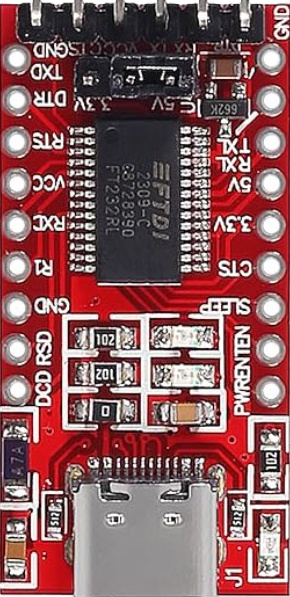
The FT232RL is a USB to serial UART interface module based on the FT232RL chip from FTDI. It is designed to provide seamless communication between a USB port and serial devices, such as microcontrollers, sensors, and other embedded systems. The module is widely used in electronics projects to enable USB connectivity for devices that lack native USB support.
Explore Projects Built with FT232RL Module


Explore Projects Built with FT232RL Module
Common Applications and Use Cases
- Programming and debugging microcontrollers (e.g., Arduino, ESP8266, ESP32)
- USB-to-TTL serial communication for embedded systems
- Interfacing with sensors and modules that use UART communication
- Data logging and serial communication with PCs
- Prototyping and testing serial devices
Technical Specifications
The FT232RL module is a versatile and reliable component with the following key specifications:
| Parameter | Value |
|---|---|
| USB Standard | USB 2.0 Full Speed |
| UART Baud Rate | 300 bps to 3 Mbps |
| Operating Voltage | 3.3V or 5V (selectable via jumper) |
| Logic Level | 3.3V or 5V (selectable via jumper) |
| Current Consumption | ~15 mA (idle) |
| Driver Support | Windows, macOS, Linux |
| Dimensions | ~36mm x 17mm |
Pin Configuration and Descriptions
The FT232RL module typically includes a 6-pin header for serial communication and power. Below is the pinout:
| Pin Name | Description |
|---|---|
| GND | Ground connection |
| VCC | Power input (3.3V or 5V, depending on jumper setting) |
| TXD | Transmit data (UART output from FT232RL to the connected device) |
| RXD | Receive data (UART input to FT232RL from the connected device) |
| DTR | Data Terminal Ready (used for auto-reset in microcontroller programming) |
| CTS | Clear to Send (optional, used for hardware flow control) |
Usage Instructions
How to Use the FT232RL Module in a Circuit
Connect the Module to Your Device:
- Connect the
TXDpin of the FT232RL module to theRXpin of your device. - Connect the
RXDpin of the FT232RL module to theTXpin of your device. - Connect the
GNDpin to the ground of your circuit. - Provide power to the module via the
VCCpin (3.3V or 5V, depending on your device).
- Connect the
Install Drivers:
- Download and install the FTDI drivers from the official FTDI website (https://ftdichip.com/).
- Ensure the drivers are properly installed on your operating system.
Connect to a PC:
- Use a USB cable to connect the FT232RL module to your computer.
- The module should appear as a virtual COM port in your system's device manager.
Test Communication:
- Use a serial terminal program (e.g., PuTTY, Tera Term, or Arduino Serial Monitor) to test communication.
- Set the baud rate and other serial parameters to match your device's configuration.
Important Considerations and Best Practices
- Voltage Selection: Ensure the module's voltage level (3.3V or 5V) matches your device's requirements. Incorrect voltage levels can damage your device.
- Cross-Check Connections: Always double-check the
TXDandRXDconnections to avoid communication issues. - Avoid Overloading: Do not exceed the module's current rating. If powering external devices, ensure the total current draw is within safe limits.
- Use DTR for Auto-Reset: When programming microcontrollers like Arduino, connect the
DTRpin to the reset pin of the microcontroller via a 0.1 µF capacitor for automatic reset during uploads.
Example: Using FT232RL with Arduino UNO
Below is an example of how to use the FT232RL module to upload code to an Arduino UNO:
Connect the FT232RL module to the Arduino UNO as follows:
TXD→RX(Pin 0 on Arduino)RXD→TX(Pin 1 on Arduino)GND→GNDDTR→RESET(via a 0.1 µF capacitor)
Open the Arduino IDE and select the correct COM port.
Upload the following code to test serial communication:
// Simple echo program for testing FT232RL communication
void setup() {
  Serial.begin(9600); // Initialize serial communication at 9600 baud
  Serial.println("FT232RL Test: Ready to echo data!");
}

void loop() {
  if (Serial.available()) { // Check if data is available to read
    char received = Serial.read(); // Read the incoming byte
    Serial.print("Echo: "); // Print "Echo:" before the received data
    Serial.println(received); // Echo the received byte back to the sender
  }
}
Open the Serial Monitor in the Arduino IDE, set the baud rate to
9600, and test the communication by typing characters.
Troubleshooting and FAQs
Common Issues and Solutions
FT232RL Module Not Detected by PC:
- Ensure the USB cable is functional and properly connected.
- Verify that the FTDI drivers are installed correctly.
- Try a different USB port or cable.
No Data Transmission:
- Check the
TXDandRXDconnections. Ensure they are not swapped. - Verify that the baud rate and serial settings match between the module and the device.
- Check the
Device Not Resetting During Upload:
- Ensure the
DTRpin is connected to the reset pin of the microcontroller via a 0.1 µF capacitor. - Check for loose connections or damaged components.
- Ensure the
Overheating or Power Issues:
- Confirm that the module's voltage level matches your device's requirements.
- Avoid powering high-current devices directly from the module.
FAQs
Q: Can the FT232RL module be used with 3.3V devices?
A: Yes, the module supports both 3.3V and 5V logic levels. Use the onboard jumper to select the appropriate voltage.
Q: Is the FT232RL module compatible with macOS and Linux?
A: Yes, the module is compatible with Windows, macOS, and Linux. Ensure the appropriate drivers are installed.
Q: Can I use the FT232RL module for SPI or I2C communication?
A: No, the FT232RL module is designed for UART (serial) communication only. For SPI or I2C, consider using other interface modules.
Q: How do I identify the correct COM port for the module?
A: After connecting the module to your PC, check the device manager (Windows) or use the ls /dev/tty* command (Linux/macOS) to find the assigned COM port.
By following this documentation, you can effectively use the FT232RL module in your projects and troubleshoot common issues with ease.