How to Use Adafruit NeoPixel NeoMatrix 8x8: Examples, Pinouts, and Specs
Introduction
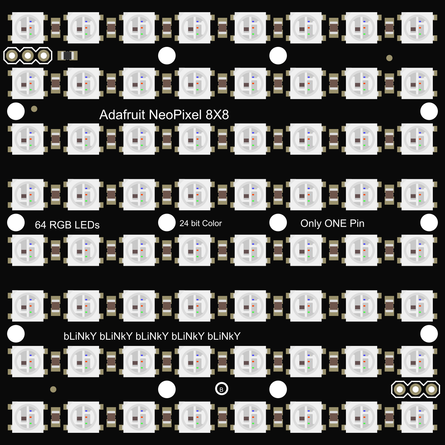
The Adafruit NeoPixel NeoMatrix 8x8 is a versatile and vibrant matrix of 64 individually addressable RGB LEDs, organized in an 8x8 grid. This component is part of the NeoPixel family, which integrates control circuitry directly into each LED, enabling users to control the color and brightness of each pixel independently. Common applications include creating colorful displays, animations, indicators, and other visually engaging projects.
Explore Projects Built with Adafruit NeoPixel NeoMatrix 8x8
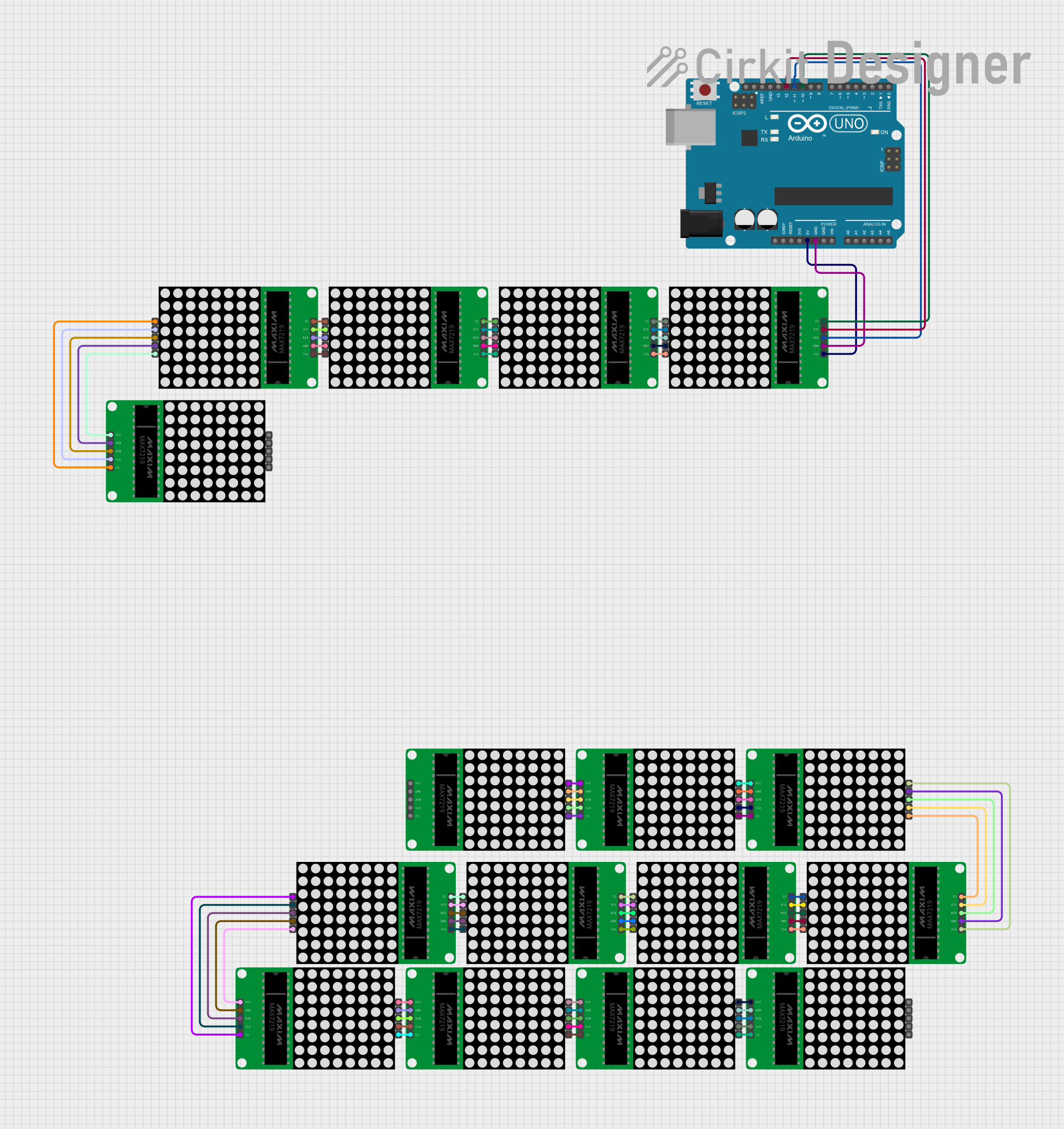
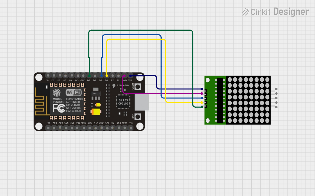
Explore Projects Built with Adafruit NeoPixel NeoMatrix 8x8
Technical Specifications
Key Technical Details
- Voltage: 5V DC
- Current: ~18mA per LED at full brightness
- Power Consumption: Up to ~1.15A at full brightness (all LEDs)
- Communication Protocol: Single-wire digital control (WS2812B protocol)
- Operating Temperature: -25°C to 80°C
Pin Configuration and Descriptions
| Pin | Description |
|---|---|
| 5V | Power supply voltage (4.5V to 5.5V) |
| GND | Ground |
| DIN | Data input from microcontroller |
| DOUT | Data output for cascading multiple matrices |
Usage Instructions
Connecting to a Circuit
- Power Supply: Connect the 5V and GND pins to a suitable 5V power supply. Ensure that the power supply can handle the maximum current draw.
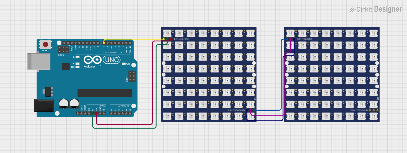
- Data Signal: Connect the DIN pin to a digital output pin on your microcontroller, such as an Arduino UNO.
- Cascading Matrices: If you're using multiple matrices, connect the DOUT pin of the first matrix to the DIN pin of the next.
Important Considerations and Best Practices
- Power Requirements: Always provide a sufficient power supply that can handle the current requirements, especially when all LEDs are at full brightness.
- Level Shifting: If using a 3.3V microcontroller, use a level shifter to bring the data signal up to 5V.
- Capacitor: Place a 1000µF capacitor across the power supply pins as close to the matrix as possible to smooth out power supply fluctuations.
- Resistor: Add a 300-500 Ohm resistor on the data input line to prevent spikes that can damage the first LED.
- Refresh Rate: To avoid flickering, maintain a high refresh rate, typically by updating the matrix at least 30 times per second.
Example Arduino Code
#include <Adafruit_NeoPixel.h>

#define PIN            6 // Define the pin for data input
#define NUMPIXELS      64 // Number of pixels in the NeoMatrix

Adafruit_NeoPixel pixels = Adafruit_NeoPixel(NUMPIXELS, PIN, NEO_GRB + NEO_KHZ800);

void setup() {
  pixels.begin(); // Initialize the NeoPixel matrix
  pixels.show(); // Initialize all pixels to 'off'
}

void loop() {
  for(int i=0; i<NUMPIXELS; i++) {
    pixels.setPixelColor(i, pixels.Color(150, 0, 90)); // Set color to purple
    pixels.show(); // Update the matrix to show the new color
    delay(50); // Delay for visibility
    pixels.setPixelColor(i, pixels.Color(0, 0, 0)); // Turn off the pixel
  }
}
Troubleshooting and FAQs
Common Issues
- LEDs Not Lighting Up: Ensure that the power supply is correctly connected and rated for the current draw. Check the data input connection and ensure the correct pin is being used in the code.
- Flickering LEDs: This can be due to an insufficient refresh rate or power supply fluctuations. Ensure the code updates the matrix frequently and that a capacitor is used to stabilize the power supply.
- Incorrect Colors: Verify that the correct color order (e.g., GRB) is specified in the code. Adjust the color order if necessary.
Solutions and Tips
- Power Supply Issues: If the LEDs are dim or flickering, consider using a separate power supply for the matrix, especially when using multiple matrices.
- Data Signal Integrity: Keep the data line as short as possible to prevent signal degradation. Use a level shifter if necessary.
- Code Debugging: Use serial output to debug the code and ensure that the correct values are being sent to the matrix.
FAQs
Q: Can I control each LED individually? A: Yes, each LED can be controlled individually with its own color and brightness.
Q: How do I cascade multiple NeoMatrix panels? A: Connect the DOUT pin of one matrix to the DIN pin of the next. Ensure your microcontroller code addresses the increased number of LEDs.
Q: What is the maximum number of matrices I can cascade? A: The maximum is limited by the power supply and the microcontroller's memory. Ensure that the power supply can handle the current for all cascaded matrices and that the microcontroller has enough memory to store the LED color data.