Cirkit Designer Logo
Cirkit Designer
Your all-in-one circuit design IDE
Home / 
Component Documentation

How to Use KY-020: Examples, Pinouts, and Specs

Image of KY-020
Cirkit Designer LogoDesign with KY-020 in Cirkit Designer

Introduction

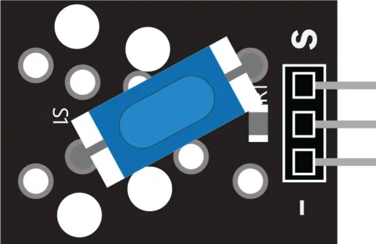
The KY-020 2-Channel Relay Module is an electronic device that allows a low voltage or low current signal to control a higher voltage circuit. It is commonly used in automation projects, home appliances control, and switching devices like lights, motors, or heaters. The module features two independent relays, each with its own circuitry and status LED, providing a visual indication of the relay operation.

Explore Projects Built with KY-020

Use Cirkit Designer to design, explore, and prototype these projects online. Some projects support real-time simulation. Click "Open Project" to start designing instantly!
Arduino UNO Controlled RGB LED Light Show with Sound Detection
Image of Voice Sensor with RGB: A project utilizing KY-020 in a practical application
This circuit features an Arduino UNO microcontroller connected to a KY-038 sound sensor module and an RGB LED with individual resistors on each color channel. The Arduino is programmed to sequentially turn on the red, green, and blue channels of the RGB LED, each for a duration of 2 seconds. The sound sensor is powered by the Arduino and its analog and digital outputs are connected to the Arduino's analog and digital pins, respectively, for sound detection and processing.
Cirkit Designer LogoOpen Project in Cirkit Designer
ESP32-Based Security System with RFID and Laser Tripwire
Image of CPE doorlock system: A project utilizing KY-020 in a practical application
This circuit is designed for a comprehensive security and access control system with motion detection, access via RFID, and a break-beam sensor. It includes a solenoid lock controlled by a relay, visual and audible alerts, and a robust power management system with solar and battery backup to ensure uninterrupted operation.
Cirkit Designer LogoOpen Project in Cirkit Designer
Arduino Nano Joystick-Controlled Bluetooth Module with Battery Power
Image of padelpro transmitter: A project utilizing KY-020 in a practical application
This circuit is a wireless joystick controller that uses an Arduino Nano to read analog signals from a KY-023 Dual Axis Joystick Module and transmits the data via an HC-05 Bluetooth Module. The system is powered by a 18650 Li-Ion battery with a rocker switch for power control.
Cirkit Designer LogoOpen Project in Cirkit Designer
Arduino UNO Controlled Joystick Interface with LCD Feedback and Audio Alert
Image of 우주게임: A project utilizing KY-020 in a practical application
This circuit features an Arduino UNO microcontroller connected to a KY-023 Dual Axis Joystick Module, an I2C LCD 16x2 Screen, a Piezo Speaker, and a Pushbutton. The joystick provides two analog inputs to the Arduino for X and Y axis control, while the pushbutton is connected to a digital input for user interaction. The LCD screen displays information via I2C communication, and the Piezo Speaker is driven by a digital output from the Arduino for audio feedback.
Cirkit Designer LogoOpen Project in Cirkit Designer

Explore Projects Built with KY-020

Use Cirkit Designer to design, explore, and prototype these projects online. Some projects support real-time simulation. Click "Open Project" to start designing instantly!
Image of Voice Sensor with RGB: A project utilizing KY-020 in a practical application
Arduino UNO Controlled RGB LED Light Show with Sound Detection
This circuit features an Arduino UNO microcontroller connected to a KY-038 sound sensor module and an RGB LED with individual resistors on each color channel. The Arduino is programmed to sequentially turn on the red, green, and blue channels of the RGB LED, each for a duration of 2 seconds. The sound sensor is powered by the Arduino and its analog and digital outputs are connected to the Arduino's analog and digital pins, respectively, for sound detection and processing.
Cirkit Designer LogoOpen Project in Cirkit Designer
Image of CPE doorlock system: A project utilizing KY-020 in a practical application
ESP32-Based Security System with RFID and Laser Tripwire
This circuit is designed for a comprehensive security and access control system with motion detection, access via RFID, and a break-beam sensor. It includes a solenoid lock controlled by a relay, visual and audible alerts, and a robust power management system with solar and battery backup to ensure uninterrupted operation.
Cirkit Designer LogoOpen Project in Cirkit Designer
Image of padelpro transmitter: A project utilizing KY-020 in a practical application
Arduino Nano Joystick-Controlled Bluetooth Module with Battery Power
This circuit is a wireless joystick controller that uses an Arduino Nano to read analog signals from a KY-023 Dual Axis Joystick Module and transmits the data via an HC-05 Bluetooth Module. The system is powered by a 18650 Li-Ion battery with a rocker switch for power control.
Cirkit Designer LogoOpen Project in Cirkit Designer
Image of 우주게임: A project utilizing KY-020 in a practical application
Arduino UNO Controlled Joystick Interface with LCD Feedback and Audio Alert
This circuit features an Arduino UNO microcontroller connected to a KY-023 Dual Axis Joystick Module, an I2C LCD 16x2 Screen, a Piezo Speaker, and a Pushbutton. The joystick provides two analog inputs to the Arduino for X and Y axis control, while the pushbutton is connected to a digital input for user interaction. The LCD screen displays information via I2C communication, and the Piezo Speaker is driven by a digital output from the Arduino for audio feedback.
Cirkit Designer LogoOpen Project in Cirkit Designer

Common Applications and Use Cases

  • Home automation systems
  • Remote control of high voltage/power devices
  • Interfacing microcontrollers with high power circuits
  • Robotics and DIY projects

Technical Specifications

Key Technical Details

  • Operating Voltage: 5V DC
  • Trigger Voltage: 0-1.5V (LOW trigger), 2.5-5V (HIGH trigger)
  • Current Rating: 10A at 250V AC or 10A at 30V DC per channel
  • Relay Type: Electromechanical
  • Number of Channels: 2
  • Control Signal: TTL compatible

Pin Configuration and Descriptions

Pin Number Description Type
1 VCC Power
2 GND Power
3 IN1 Control
4 IN2 Control
5 Relay 1 Normally Open (NO) Switch
6 Relay 1 Common (COM) Switch
7 Relay 1 Normally Closed (NC) Switch
8 Relay 2 Normally Open (NO) Switch
9 Relay 2 Common (COM) Switch
10 Relay 2 Normally Closed (NC) Switch

Usage Instructions

How to Use the Component in a Circuit

  1. Connect the VCC pin to a 5V power supply.
  2. Connect the GND pin to the ground of the power supply.
  3. Connect the IN1 and IN2 pins to the control signals (e.g., from a microcontroller).
  4. Connect the device you want to control to the NO or NC and COM pins of the relay.

Important Considerations and Best Practices

  • Ensure the power supply does not exceed the recommended voltage.
  • Do not exceed the current rating of the relays.
  • Use flyback diodes when switching inductive loads to prevent back EMF damage.
  • Isolate the low voltage control circuit from the high voltage power circuit.

Example Code for Arduino UNO

// Define relay control pins
const int relay1Pin = 2;
const int relay2Pin = 3;

void setup() {
  // Set relay pins as outputs
  pinMode(relay1Pin, OUTPUT);
  pinMode(relay2Pin, OUTPUT);
}

void loop() {
  // Turn on relay 1
  digitalWrite(relay1Pin, HIGH);
  delay(1000); // Wait for 1 second
  // Turn off relay 1
  digitalWrite(relay1Pin, LOW);
  delay(1000); // Wait for 1 second
  
  // Turn on relay 2
  digitalWrite(relay2Pin, HIGH);
  delay(1000); // Wait for 1 second
  // Turn off relay 2
  digitalWrite(relay2Pin, LOW);
  delay(1000); // Wait for 1 second
}

Troubleshooting and FAQs

Common Issues

  • Relay not activating: Check the control signal voltage and connections.
  • Intermittent operation: Verify the power supply is stable and within specifications.
  • Clicking sound but no switching: Inspect the load and ensure it does not exceed the relay's rating.

Solutions and Tips for Troubleshooting

  • Ensure all connections are secure and free from corrosion.
  • Use a multimeter to check the continuity of the relay contacts.
  • Test the control signal with an LED to confirm the microcontroller is functioning correctly.

FAQs

Q: Can I control the KY-020 with a 3.3V microcontroller? A: Yes, but ensure the control signal meets the LOW trigger voltage threshold.

Q: Is it safe to switch AC mains with this module? A: Yes, but take proper precautions to avoid electric shock and adhere to electrical safety standards.

Q: Can I use PWM to control the relays? A: No, relays require a stable HIGH or LOW signal to switch states. PWM may cause erratic behavior.