How to Use STM32F746GDISCO: Examples, Pinouts, and Specs
Introduction
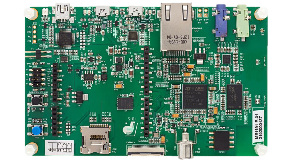
The STM32F746G-DISCO is a discovery board developed by STMicroelectronics, featuring the STM32F746NG microcontroller. This microcontroller is based on the high-performance ARM Cortex-M7 core, operating at up to 216 MHz. The board is designed to simplify the development and prototyping of embedded applications, offering a wide range of integrated peripherals, including a 4.3-inch TFT LCD with capacitive touch, audio codec, MEMS microphone, and various connectivity options.
Explore Projects Built with STM32F746GDISCO


Explore Projects Built with STM32F746GDISCO
Common Applications and Use Cases
- Graphical user interface (GUI) development
- Audio processing and playback
- IoT and connected devices
- Sensor-based applications
- Prototyping for industrial and consumer electronics
Technical Specifications
Key Technical Details
| Feature | Specification |
|---|---|
| Microcontroller | STM32F746NGH6 (ARM Cortex-M7, 32-bit, 216 MHz) |
| Flash Memory | 1 MB |
| RAM | 320 KB |
| LCD Display | 4.3-inch TFT LCD with capacitive touch (480x272 resolution) |
| Audio Codec | WM8994ECS/R with stereo audio output and input |
| Connectivity | USB OTG FS, Ethernet, microSD card slot |
| Sensors | ST MEMS microphone (MP34DT01) |
| Debugging | ST-LINK/V2-1 debugger/programmer integrated |
| Power Supply | USB-powered (5V) or external power supply (7V-12V via VIN pin) |
| Dimensions | 154 mm x 86 mm |
Pin Configuration and Descriptions
The STM32F746G-DISCO board provides access to the STM32F746NG microcontroller's GPIO pins via headers. Below is a summary of the key pin configurations:
GPIO Header Pinout
| Pin Number | Pin Name | Functionality | Notes |
|---|---|---|---|
| 1 | 3V3 | 3.3V Power Output | Provides 3.3V for external components |
| 2 | GND | Ground | Common ground for the circuit |
| 3 | PA0 | GPIO, ADC Input, WKUP1 | Configurable as digital/analog input |
| 4 | PA1 | GPIO, ADC Input | Configurable as digital/analog input |
| 5 | PB6 | GPIO, I2C1_SCL | I2C clock line |
| 6 | PB7 | GPIO, I2C1_SDA | I2C data line |
| 7 | PC10 | GPIO, UART4_TX | UART transmit |
| 8 | PC11 | GPIO, UART4_RX | UART receive |
| 9 | PD12 | GPIO, PWM Output | Can be used for PWM signals |
| 10 | PD13 | GPIO, PWM Output | Can be used for PWM signals |
Additional Interfaces
| Interface | Description |
|---|---|
| USB OTG FS | USB Full-Speed interface for device/host communication |
| Ethernet | 10/100 Mbps Ethernet interface |
| microSD Slot | Supports microSD cards for data storage |
| Audio Jack | 3.5mm stereo audio output |
Usage Instructions
How to Use the STM32F746G-DISCO in a Circuit
Powering the Board:
- Connect the board to a PC using a micro-USB cable for power and programming.
- Alternatively, use an external power supply (7V-12V) via the VIN pin.
Programming the Board:
- Use the integrated ST-LINK/V2-1 debugger to program the microcontroller.
- Compatible IDEs include STM32CubeIDE, Keil MDK, and IAR Embedded Workbench.
Connecting Peripherals:
- Use the GPIO headers to connect external sensors, actuators, or other devices.
- For audio applications, connect headphones or speakers to the 3.5mm audio jack.
Using the LCD Display:
- The 4.3-inch TFT LCD can be used for graphical interfaces.
- Libraries such as TouchGFX or STM32CubeF7 provide tools for GUI development.
Using the microSD Slot:
- Insert a microSD card for data logging or file storage.
- Use the FATFS library for file system management.
Important Considerations and Best Practices
- Voltage Levels: Ensure that external components connected to GPIO pins operate at 3.3V logic levels to avoid damage.
- Clock Configuration: Properly configure the system clock in your firmware to utilize the full performance of the Cortex-M7 core.
- Peripheral Initialization: Use the STM32 HAL (Hardware Abstraction Layer) or LL (Low Layer) drivers to initialize peripherals.
- Debugging: Use the integrated ST-LINK/V2-1 for debugging and real-time variable monitoring.
Example Code for Arduino IDE
The STM32F746G-DISCO can be programmed using the Arduino IDE with the STM32 core installed. Below is an example of toggling an LED connected to pin PA0:
// Include the STM32 HAL library
#include <STM32F7xx.h>

// Define the LED pin
#define LED_PIN PA0

void setup() {
  // Initialize the LED pin as an output
  pinMode(LED_PIN, OUTPUT);
}

void loop() {
  // Toggle the LED on and off
  digitalWrite(LED_PIN, HIGH); // Turn the LED on
  delay(500);                  // Wait for 500 ms
  digitalWrite(LED_PIN, LOW);  // Turn the LED off
  delay(500);                  // Wait for 500 ms
}
Troubleshooting and FAQs
Common Issues and Solutions
The board does not power on:
- Ensure the USB cable is properly connected and functional.
- If using an external power supply, verify the voltage is within the 7V-12V range.
Unable to program the board:
- Check that the ST-LINK/V2-1 driver is installed on your PC.
- Ensure the board is in programming mode and the correct COM port is selected.
LCD display is not working:
- Verify that the LCD initialization code is included in your firmware.
- Check the ribbon cable connection between the LCD and the board.
GPIO pins are not responding:
- Confirm that the pins are correctly configured in your code (input/output mode).
- Ensure external components connected to the pins are functional.
FAQs
Q: Can I use the STM32F746G-DISCO for IoT applications?
A: Yes, the board supports Ethernet and USB connectivity, making it suitable for IoT projects. You can also add Wi-Fi or Bluetooth modules via GPIO or UART.
Q: Is the board compatible with Arduino libraries?
A: With the STM32 core installed in the Arduino IDE, you can use many Arduino libraries, but some may require modifications for compatibility.
Q: How do I update the ST-LINK firmware?
A: Use the ST-LINK Utility software provided by STMicroelectronics to update the firmware.
Q: Can I use the board for audio processing?
A: Yes, the integrated audio codec and MEMS microphone make it ideal for audio applications such as voice recognition or playback.