How to Use LoRa RYLR896: Examples, Pinouts, and Specs
Introduction
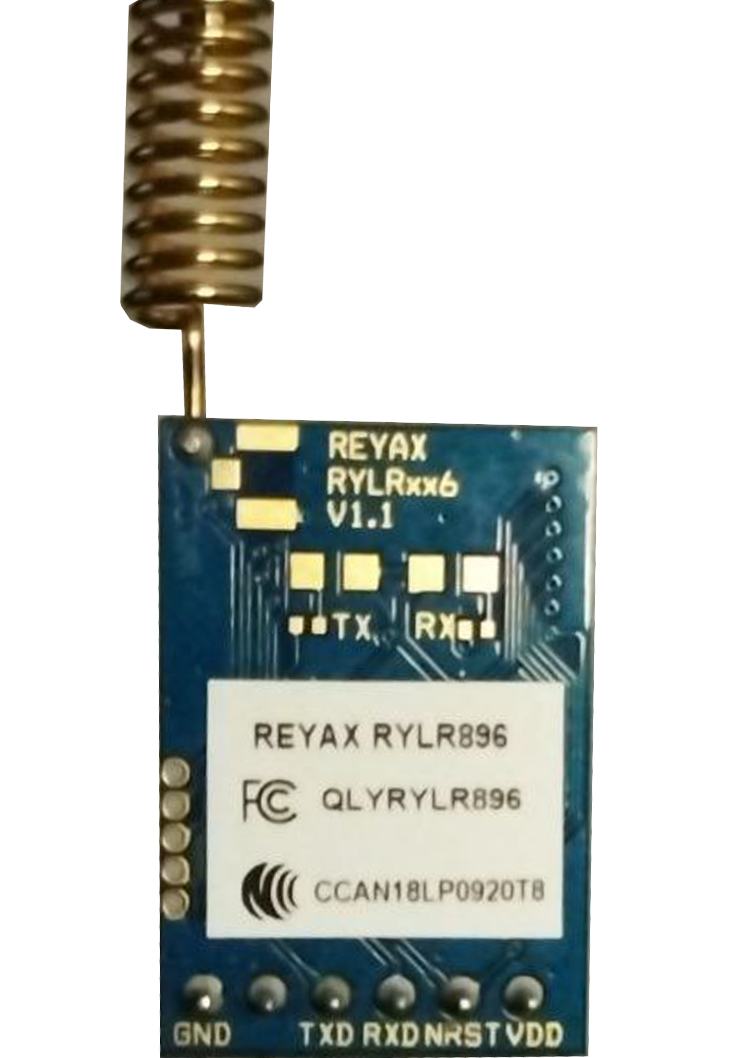
The LoRa RYLR896 is a low-power, long-range transceiver module manufactured by REYAX. It is designed for wireless communication in the 433MHz, 868MHz, and 915MHz frequency bands. Utilizing LoRa (Long Range) modulation technology, the RYLR896 achieves extended communication range and low power consumption, making it an excellent choice for IoT (Internet of Things) applications.
Explore Projects Built with LoRa RYLR896


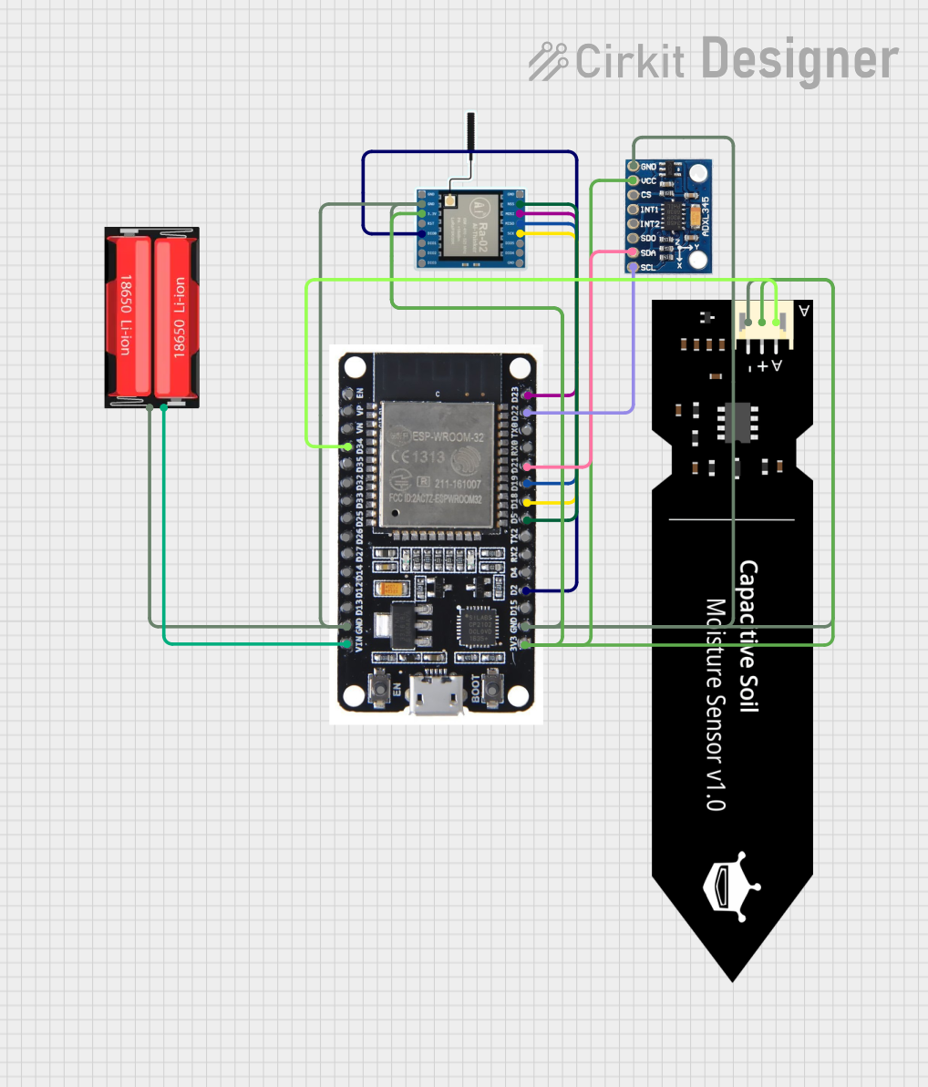
Explore Projects Built with LoRa RYLR896
Common Applications and Use Cases
- Smart agriculture (e.g., soil moisture monitoring, weather stations)
- Industrial automation and control systems
- Smart cities (e.g., parking sensors, street lighting control)
- Home automation and security systems
- Asset tracking and fleet management
- Environmental monitoring (e.g., air quality sensors)
Technical Specifications
The following table outlines the key technical details of the RYLR896 module:
| Parameter | Specification |
|---|---|
| Frequency Bands | 433MHz, 868MHz, 915MHz |
| Modulation Technology | LoRa (Long Range) |
| Communication Range | Up to 15 km (line of sight) |
| Operating Voltage | 2.8V to 3.6V |
| Operating Current | 10.5mA (transmit), 9.0mA (receive) |
| Sleep Current | < 1.0µA |
| Data Rate | 0.3 kbps to 37.5 kbps |
| Interface | UART (3.3V logic level) |
| Operating Temperature | -40°C to +85°C |
| Dimensions | 25mm x 16mm x 2.2mm |
Pin Configuration and Descriptions
The RYLR896 module has a total of 8 pins. The pin configuration and their descriptions are provided in the table below:
| Pin Number | Pin Name | Description |
|---|---|---|
| 1 | VCC | Power supply input (2.8V to 3.6V) |
| 2 | GND | Ground |
| 3 | TXD | UART Transmit (3.3V logic level) |
| 4 | RXD | UART Receive (3.3V logic level) |
| 5 | RESET | Module reset (active low) |
| 6 | WAKE_UP | Wake-up pin for exiting sleep mode (active high) |
| 7 | ANT | Antenna connection |
| 8 | NC | Not connected |
Usage Instructions
How to Use the RYLR896 in a Circuit
- Power Supply: Connect the VCC pin to a regulated 3.3V power source and the GND pin to ground.
- UART Communication: Connect the TXD and RXD pins to the UART pins of your microcontroller (e.g., Arduino UNO). Use a logic level shifter if your microcontroller operates at 5V logic.
- Antenna: Attach a suitable antenna to the ANT pin to ensure optimal signal transmission and reception.
- Reset and Wake-Up: Use the RESET pin to reset the module and the WAKE_UP pin to bring the module out of sleep mode if necessary.
Important Considerations and Best Practices
- Antenna Placement: Ensure the antenna is placed away from metal objects and other sources of interference to maximize range.
- Power Supply: Use a stable and noise-free power supply to avoid communication issues.
- UART Settings: Configure the UART interface with the following settings:
- Baud rate: 9600 bps (default)
- Data bits: 8
- Parity: None
- Stop bits: 1
- Command Mode: The RYLR896 operates using AT commands. Ensure proper formatting of commands (e.g., ending with
\r\n).
Example: Connecting RYLR896 to Arduino UNO
Below is an example of how to use the RYLR896 module with an Arduino UNO to send a simple message:
Circuit Diagram
- Connect VCC to the 3.3V pin on the Arduino.
- Connect GND to the GND pin on the Arduino.
- Connect TXD to pin 10 (Arduino RX via software serial).
- Connect RXD to pin 11 (Arduino TX via software serial).
Arduino Code
#include <SoftwareSerial.h>

// Define software serial pins for RYLR896
SoftwareSerial loraSerial(10, 11); // RX, TX

void setup() {
  // Initialize serial communication
  Serial.begin(9600); // For debugging
  loraSerial.begin(9600); // For RYLR896 communication

  // Send initialization command to RYLR896
  loraSerial.println("AT+ADDRESS=1"); // Set device address to 1
  delay(100);
  loraSerial.println("AT+NETWORKID=5"); // Set network ID to 5
  delay(100);
  loraSerial.println("AT+SEND=2,5,Hello");
  // Send "Hello" to device address 2 with 5 bytes of data
}

void loop() {
  // Check for incoming data from RYLR896
  if (loraSerial.available()) {
    String receivedData = loraSerial.readString();
    Serial.println("Received: " + receivedData); // Print received data
  }
}
Notes:
- Replace
2in theAT+SENDcommand with the address of the receiving device. - Ensure all devices in the network share the same Network ID.
Troubleshooting and FAQs
Common Issues and Solutions
No Response from Module
- Ensure the module is powered correctly (check VCC and GND connections).
- Verify UART connections and baud rate settings.
- Check if the module is in sleep mode; use the WAKE_UP pin to wake it up.
Poor Communication Range
- Ensure the antenna is properly connected and positioned.
- Avoid obstructions and interference sources in the communication path.
AT Commands Not Working
- Ensure commands are terminated with
\r\n. - Check the UART logic level (use a level shifter if necessary).
- Ensure commands are terminated with
Data Loss or Corruption
- Verify that all devices in the network use the same Network ID.
- Check for UART baud rate mismatches.
FAQs
Q: Can the RYLR896 operate at 5V?
A: No, the RYLR896 operates at 2.8V to 3.6V. Use a voltage regulator or level shifter for 5V systems.
Q: What is the maximum range of the RYLR896?
A: The module can achieve up to 15 km range in line-of-sight conditions. Actual range depends on environmental factors.
Q: How do I reset the module?
A: Pull the RESET pin low momentarily to reset the module.
Q: Can I use the RYLR896 with other LoRa modules?
A: Yes, as long as the other modules support the same frequency band and LoRa protocol. Ensure they share the same Network ID and settings.