How to Use ESP32 Relay Board 8ch: Examples, Pinouts, and Specs
Introduction
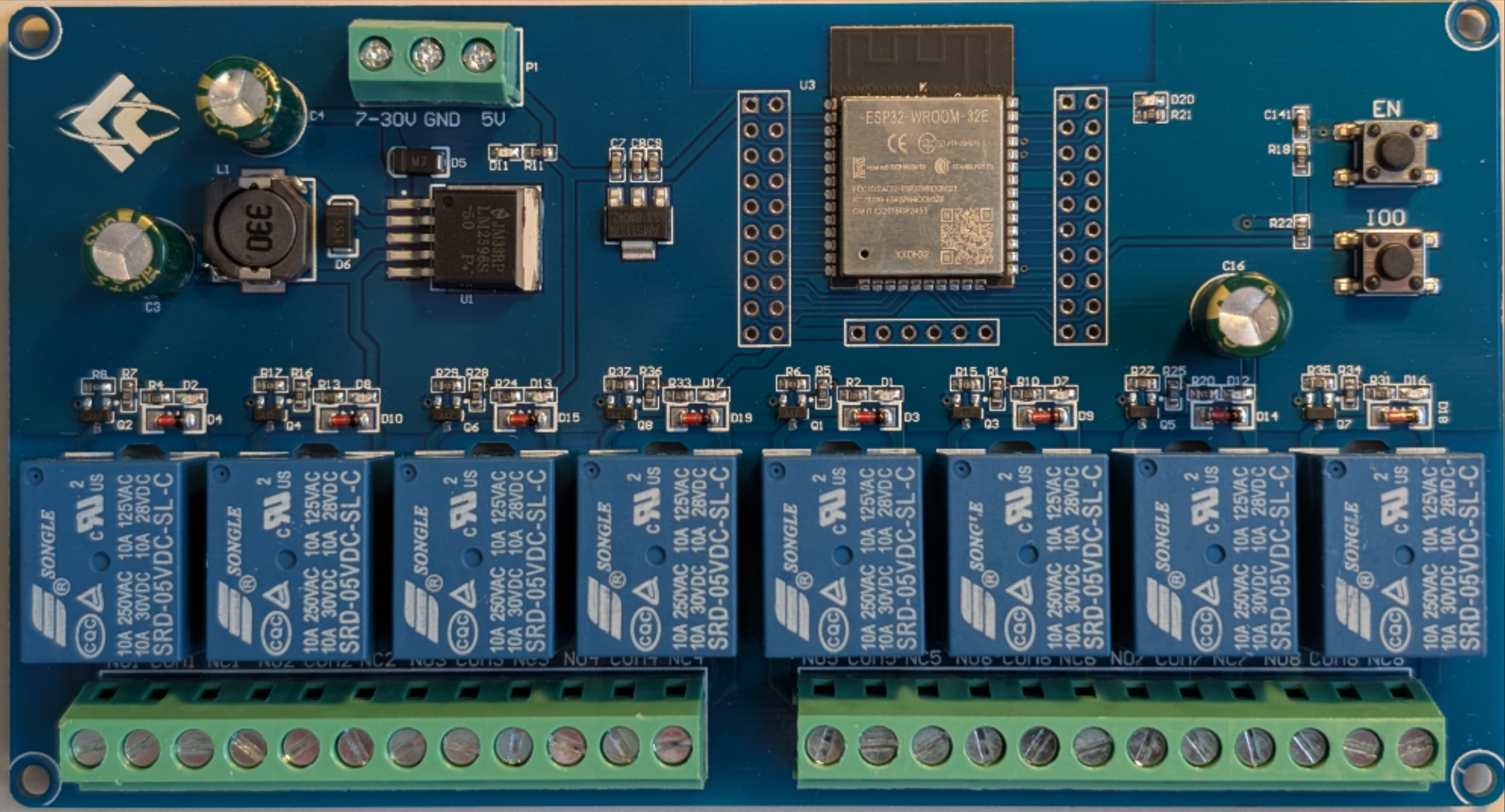
The ESP32 Relay Board 8ch is an 8-channel relay module designed to work seamlessly with the ESP32 microcontroller. This board allows users to control multiple high-voltage devices such as lights, fans, and other appliances, making it an ideal choice for home automation, industrial control systems, and IoT projects. Each relay on the board can be independently controlled, enabling flexible and efficient device management.
Explore Projects Built with ESP32 Relay Board 8ch


Explore Projects Built with ESP32 Relay Board 8ch
Common Applications and Use Cases
- Home Automation: Control lights, fans, and other household appliances remotely.
- Industrial Automation: Manage machinery and equipment in industrial settings.
- IoT Projects: Integrate with sensors and cloud platforms for smart device control.
- Prototyping: Develop and test multi-device control systems.
Technical Specifications
The following table outlines the key technical details of the ESP32 Relay Board 8ch:
| Parameter | Specification |
|---|---|
| Operating Voltage | 5V (Relay Power) / 3.3V (ESP32 Control Logic) |
| Relay Channels | 8 |
| Relay Type | SPDT (Single Pole Double Throw) |
| Maximum Load Voltage | 250V AC / 30V DC |
| Maximum Load Current | 10A |
| Control Signal Logic | Active LOW |
| Communication | GPIO pins of ESP32 |
| Dimensions | ~140mm x 50mm x 20mm |
| Isolation | Optocoupler-based isolation for each relay channel |
Pin Configuration and Descriptions
The ESP32 Relay Board 8ch has the following pin configuration:
Input Pins (Control Signals)
| Pin Name | Description |
|---|---|
| IN1 | Control signal for Relay 1 (Active LOW) |
| IN2 | Control signal for Relay 2 (Active LOW) |
| IN3 | Control signal for Relay 3 (Active LOW) |
| IN4 | Control signal for Relay 4 (Active LOW) |
| IN5 | Control signal for Relay 5 (Active LOW) |
| IN6 | Control signal for Relay 6 (Active LOW) |
| IN7 | Control signal for Relay 7 (Active LOW) |
| IN8 | Control signal for Relay 8 (Active LOW) |
Power and Ground Pins
| Pin Name | Description |
|---|---|
| VCC | 5V Power Supply for the relay module |
| GND | Ground connection |
Output Terminals (Relay Contacts)
Each relay has three output terminals:
| Terminal | Description |
|---|---|
| NO | Normally Open contact |
| NC | Normally Closed contact |
| COM | Common contact |
Usage Instructions
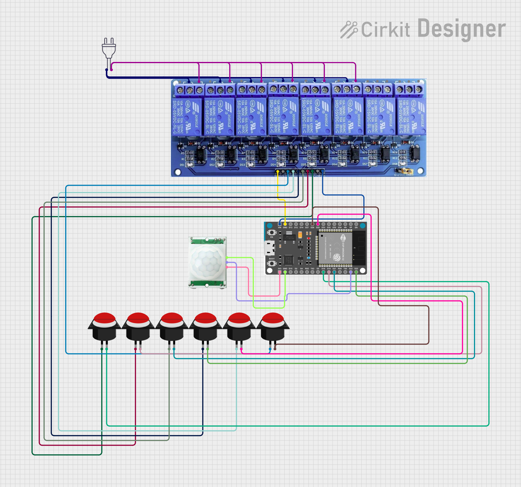
How to Use the ESP32 Relay Board 8ch in a Circuit
- Power the Relay Board: Connect the VCC pin to a 5V power source and the GND pin to ground.
- Connect the ESP32: Use GPIO pins on the ESP32 to control the relay inputs (IN1 to IN8). Ensure the ESP32 shares a common ground with the relay board.
- Connect the Load: Wire the devices you want to control to the relay output terminals (NO, NC, and COM) based on your desired switching configuration.
- Write the Code: Program the ESP32 to send control signals (LOW to activate, HIGH to deactivate) to the relay inputs.
Important Considerations and Best Practices
- Isolation: Ensure proper electrical isolation between the high-voltage side and the low-voltage control side to prevent damage to the ESP32.
- Power Supply: Use a stable 5V power source for the relay board to avoid erratic behavior.
- Load Ratings: Do not exceed the maximum voltage and current ratings of the relays.
- Active LOW Logic: Remember that the relays are activated when the control signal is LOW.
Example Code for Arduino IDE
Below is an example code snippet to control the ESP32 Relay Board 8ch using an ESP32 microcontroller:
// Define GPIO pins for the relay inputs
#define RELAY1  25  // GPIO pin connected to IN1
#define RELAY2  26  // GPIO pin connected to IN2
#define RELAY3  27  // GPIO pin connected to IN3
#define RELAY4  14  // GPIO pin connected to IN4
#define RELAY5  12  // GPIO pin connected to IN5
#define RELAY6  13  // GPIO pin connected to IN6
#define RELAY7  32  // GPIO pin connected to IN7
#define RELAY8  33  // GPIO pin connected to IN8

void setup() {
  // Initialize relay pins as outputs
  pinMode(RELAY1, OUTPUT);
  pinMode(RELAY2, OUTPUT);
  pinMode(RELAY3, OUTPUT);
  pinMode(RELAY4, OUTPUT);
  pinMode(RELAY5, OUTPUT);
  pinMode(RELAY6, OUTPUT);
  pinMode(RELAY7, OUTPUT);
  pinMode(RELAY8, OUTPUT);

  // Set all relays to OFF (HIGH state)
  digitalWrite(RELAY1, HIGH);
  digitalWrite(RELAY2, HIGH);
  digitalWrite(RELAY3, HIGH);
  digitalWrite(RELAY4, HIGH);
  digitalWrite(RELAY5, HIGH);
  digitalWrite(RELAY6, HIGH);
  digitalWrite(RELAY7, HIGH);
  digitalWrite(RELAY8, HIGH);
}

void loop() {
  // Example: Turn on Relay 1 for 2 seconds, then turn it off
  digitalWrite(RELAY1, LOW);  // Activate Relay 1
  delay(2000);                // Wait for 2 seconds
  digitalWrite(RELAY1, HIGH); // Deactivate Relay 1
  delay(2000);                // Wait for 2 seconds
}
Troubleshooting and FAQs
Common Issues and Solutions
Relays Not Activating:
- Cause: Incorrect wiring or insufficient power supply.
- Solution: Verify the wiring connections and ensure the relay board is powered with a stable 5V source.
ESP32 Resets When Relays Switch:
- Cause: Voltage spikes or insufficient power supply to the ESP32.
- Solution: Use a separate power supply for the relay board and the ESP32. Add a flyback diode across the relay coil if not already present.
Relays Stuck in ON/OFF State:
- Cause: Faulty relay or incorrect control signal logic.
- Solution: Check the control signals and replace the faulty relay if necessary.
High Voltage Load Not Switching:
- Cause: Incorrect wiring of the load to the relay terminals.
- Solution: Double-check the wiring to the NO, NC, and COM terminals.
FAQs
Can I use a 3.3V power supply for the relay board?
No, the relay board requires a 5V power supply for proper operation.How many relays can I control simultaneously?
You can control all 8 relays simultaneously, provided your power supply can handle the current draw.Is the relay board compatible with other microcontrollers?
Yes, the relay board can be used with other microcontrollers like Arduino, Raspberry Pi, etc., as long as the control logic matches.What precautions should I take when switching high-voltage loads?
Ensure proper insulation, use appropriate wiring, and avoid exceeding the relay's voltage and current ratings.