Cirkit Designer Logo
Cirkit Designer
Your all-in-one circuit design IDE
Home / 
Component Documentation

How to Use Microwave Radar Doppler Motion Sensor Module: Examples, Pinouts, and Specs

Image of Microwave Radar Doppler Motion Sensor Module
Cirkit Designer LogoDesign with Microwave Radar Doppler Motion Sensor Module in Cirkit Designer

Introduction

The Microwave Radar Doppler Motion Sensor Module is a highly sensitive motion detection device that operates using microwave radar technology. It detects motion by measuring the Doppler effect of reflected microwave signals, making it capable of sensing movement through non-metallic objects such as walls, glass, and plastic. Unlike traditional PIR (Passive Infrared) sensors, this module is not affected by ambient temperature changes, making it suitable for a wide range of environments.

Explore Projects Built with Microwave Radar Doppler Motion Sensor Module

Use Cirkit Designer to design, explore, and prototype these projects online. Some projects support real-time simulation. Click "Open Project" to start designing instantly!
Arduino Mega 2560 and ESP32 CAM Based Motion Detection and RFID Security System
Image of Arduino Mega Circuit: A project utilizing Microwave Radar Doppler Motion Sensor Module in a practical application
This circuit is designed for a multi-sensor motion detection system with image capture and RFID reading capabilities. It uses an Arduino Mega 2560 as the central processing unit, interfacing with microwave radar motion sensors, an ESP32 CAM, and RFID boards. Power management is handled by voltage regulators and DC-DC converters, and an Arduino MKR WiFi 1010 is included for potential wireless communication.
Cirkit Designer LogoOpen Project in Cirkit Designer
Arduino-Based Doppler Radar with RF Transmission and LCD Display
Image of Doppler Radar: A project utilizing Microwave Radar Doppler Motion Sensor Module in a practical application
This circuit features an Arduino UNO microcontroller interfaced with an RF 433 MHz Transmitter, a Transmitter RF Module, an LCD screen with I2C communication, and a doppler radar sensor. The Arduino controls the RF transmission and processes the doppler radar's signal, likely for motion detection purposes. The LCD screen is used to display information or statuses, and the RF modules enable wireless communication, possibly to transmit the processed radar data.
Cirkit Designer LogoOpen Project in Cirkit Designer
Raspberry Pi Pico W-Based Smart Home Automation System with Motion Detection and Environmental Monitoring
Image of Smart Home Automation 1: A project utilizing Microwave Radar Doppler Motion Sensor Module in a practical application
This circuit features a Raspberry Pi Pico W microcontroller connected to various sensors and actuators, including a DHT11 temperature and humidity sensor, an RCWL-0516 microwave radar motion sensor, a photocell (LDR) with a resistor for light detection, and a two-channel relay controlling a bulb and a fan. The microcontroller runs code to monitor environmental conditions and motion, displaying information on an LCD and allowing remote control via MQTT messages over Wi-Fi. It supports both automatic sensor-based operation and remote app control, with pushbuttons to switch between modes.
Cirkit Designer LogoOpen Project in Cirkit Designer
Raspberry Pi Zero W Obstacle Detection and SOS Alert System with LiDAR and Radar Sensors
Image of p1: A project utilizing Microwave Radar Doppler Motion Sensor Module in a practical application
This circuit integrates a Raspberry Pi Zero W with a LiDAR sensor, radar motion sensor, vibration motor, and an arcade button to create a real-time obstacle detection and alert system. The system provides immediate feedback via a vibration motor and buzzer when obstacles are detected and triggers an SOS alert when the button is pressed.
Cirkit Designer LogoOpen Project in Cirkit Designer

Explore Projects Built with Microwave Radar Doppler Motion Sensor Module

Use Cirkit Designer to design, explore, and prototype these projects online. Some projects support real-time simulation. Click "Open Project" to start designing instantly!
Image of Arduino Mega Circuit: A project utilizing Microwave Radar Doppler Motion Sensor Module in a practical application
Arduino Mega 2560 and ESP32 CAM Based Motion Detection and RFID Security System
This circuit is designed for a multi-sensor motion detection system with image capture and RFID reading capabilities. It uses an Arduino Mega 2560 as the central processing unit, interfacing with microwave radar motion sensors, an ESP32 CAM, and RFID boards. Power management is handled by voltage regulators and DC-DC converters, and an Arduino MKR WiFi 1010 is included for potential wireless communication.
Cirkit Designer LogoOpen Project in Cirkit Designer
Image of Doppler Radar: A project utilizing Microwave Radar Doppler Motion Sensor Module in a practical application
Arduino-Based Doppler Radar with RF Transmission and LCD Display
This circuit features an Arduino UNO microcontroller interfaced with an RF 433 MHz Transmitter, a Transmitter RF Module, an LCD screen with I2C communication, and a doppler radar sensor. The Arduino controls the RF transmission and processes the doppler radar's signal, likely for motion detection purposes. The LCD screen is used to display information or statuses, and the RF modules enable wireless communication, possibly to transmit the processed radar data.
Cirkit Designer LogoOpen Project in Cirkit Designer
Image of Smart Home Automation 1: A project utilizing Microwave Radar Doppler Motion Sensor Module in a practical application
Raspberry Pi Pico W-Based Smart Home Automation System with Motion Detection and Environmental Monitoring
This circuit features a Raspberry Pi Pico W microcontroller connected to various sensors and actuators, including a DHT11 temperature and humidity sensor, an RCWL-0516 microwave radar motion sensor, a photocell (LDR) with a resistor for light detection, and a two-channel relay controlling a bulb and a fan. The microcontroller runs code to monitor environmental conditions and motion, displaying information on an LCD and allowing remote control via MQTT messages over Wi-Fi. It supports both automatic sensor-based operation and remote app control, with pushbuttons to switch between modes.
Cirkit Designer LogoOpen Project in Cirkit Designer
Image of p1: A project utilizing Microwave Radar Doppler Motion Sensor Module in a practical application
Raspberry Pi Zero W Obstacle Detection and SOS Alert System with LiDAR and Radar Sensors
This circuit integrates a Raspberry Pi Zero W with a LiDAR sensor, radar motion sensor, vibration motor, and an arcade button to create a real-time obstacle detection and alert system. The system provides immediate feedback via a vibration motor and buzzer when obstacles are detected and triggers an SOS alert when the button is pressed.
Cirkit Designer LogoOpen Project in Cirkit Designer

Common Applications

  • Security systems for motion detection
  • Automatic lighting control
  • Smart home automation
  • Industrial automation systems
  • Robotics and object tracking

Technical Specifications

Below are the key technical details of the Microwave Radar Doppler Motion Sensor Module:

Parameter Value
Operating Voltage 4.0V to 28.0V DC
Operating Current ≤ 3mA
Detection Range 5 to 15 meters (adjustable)
Operating Frequency 10.525 GHz
Output Voltage (High) 3.3V
Output Voltage (Low) 0V
Detection Angle 360° (omnidirectional)
Operating Temperature -20°C to +80°C
Dimensions ~35mm x 17mm x 8mm

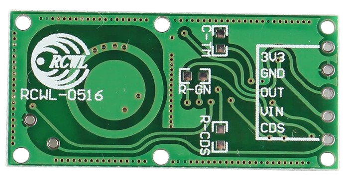
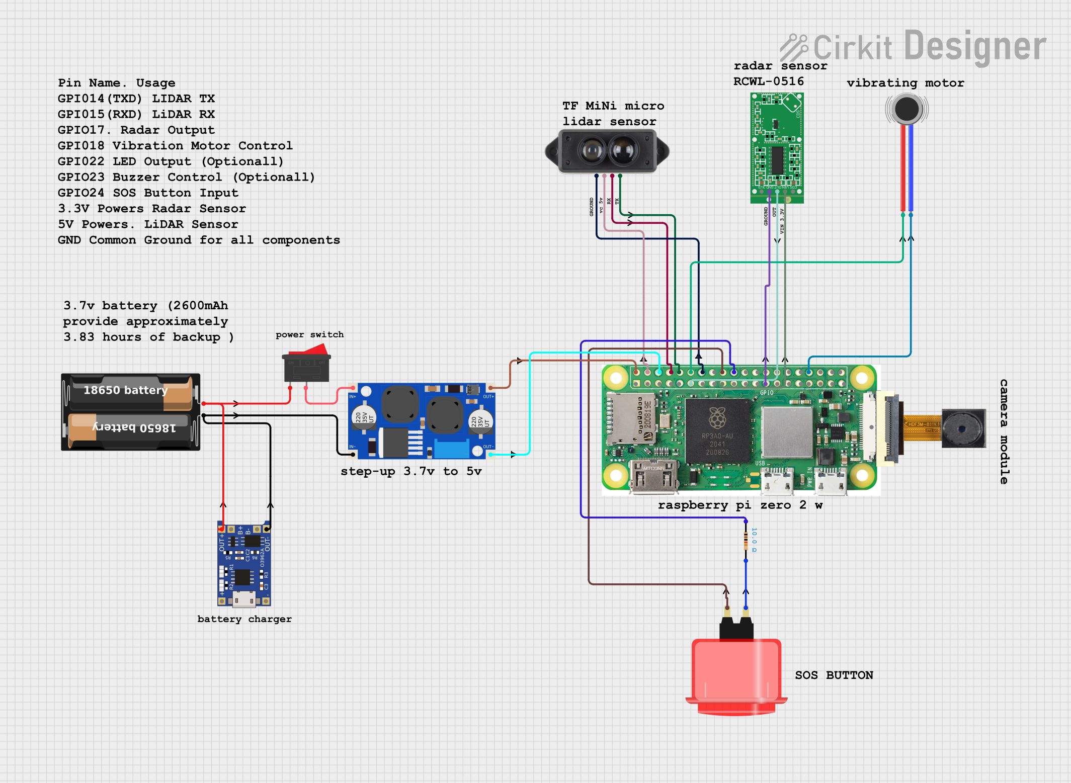
Pin Configuration and Descriptions

The module typically has three or four pins, depending on the model. Below is the pin configuration:

Pin Name Description
1 VCC Power supply input (4.0V to 28.0V DC). Connect to the positive terminal of the power source.
2 GND Ground. Connect to the negative terminal of the power source.
3 OUT Output signal pin. Outputs HIGH (3.3V) when motion is detected, otherwise LOW (0V).
4* EN (Enable) Optional pin for enabling/disabling the module (not present on all models).

*Note: The EN pin is optional and may not be available on all versions of the module.

Usage Instructions

How to Use the Module in a Circuit

  1. Power the Module: Connect the VCC pin to a DC power source (4.0V to 28.0V) and the GND pin to ground.
  2. Connect the Output: Use the OUT pin to interface with a microcontroller, relay, or other control circuit. The pin will output a HIGH signal (3.3V) when motion is detected.
  3. Adjust Sensitivity and Range: Some modules include potentiometers or jumpers to adjust the detection range and sensitivity. Refer to the specific module's datasheet for details.
  4. Placement: Install the module in a location where it can detect motion effectively. Avoid placing it near large metal objects, as they may interfere with the microwave signals.

Example: Connecting to an Arduino UNO

Below is an example of how to connect the Microwave Radar Doppler Motion Sensor Module to an Arduino UNO and read motion detection signals.

Circuit Diagram

  • Connect the VCC pin of the module to the Arduino's 5V pin.
  • Connect the GND pin of the module to the Arduino's GND pin.
  • Connect the OUT pin of the module to a digital input pin on the Arduino (e.g., D2).

Arduino Code

// Define the pin connected to the sensor's OUT pin
const int motionPin = 2; // Digital pin 2
const int ledPin = 13;   // Built-in LED pin for indication

void setup() {
  pinMode(motionPin, INPUT); // Set motionPin as input
  pinMode(ledPin, OUTPUT);   // Set ledPin as output
  Serial.begin(9600);        // Initialize serial communication
}

void loop() {
  int motionDetected = digitalRead(motionPin); // Read the sensor output

  if (motionDetected == HIGH) {
    // Motion detected
    digitalWrite(ledPin, HIGH); // Turn on the LED
    Serial.println("Motion detected!");
  } else {
    // No motion detected
    digitalWrite(ledPin, LOW); // Turn off the LED
    Serial.println("No motion.");
  }

  delay(500); // Wait for 500ms before the next reading
}

Important Considerations and Best Practices

  • Avoid Interference: Keep the module away from large metal objects or other devices operating at similar frequencies (e.g., Wi-Fi routers).
  • Power Supply: Use a stable DC power source to ensure reliable operation.
  • Environmental Factors: The module can detect motion through non-metallic objects, but thick walls or dense materials may reduce its range.
  • Testing: Test the module in the intended environment to ensure proper detection and adjust sensitivity as needed.

Troubleshooting and FAQs

Common Issues and Solutions

  1. No Motion Detected

    • Cause: Incorrect wiring or insufficient power supply.
    • Solution: Double-check the wiring and ensure the power supply voltage is within the specified range.
  2. False Triggers

    • Cause: Environmental interference or high sensitivity settings.
    • Solution: Adjust the sensitivity or relocate the module to reduce interference.
  3. Short Detection Range

    • Cause: Obstructions or improper placement.
    • Solution: Ensure the module is not obstructed and is placed in an open area.
  4. Output Signal Stuck HIGH or LOW

    • Cause: Faulty module or incorrect connections.
    • Solution: Test the module with a multimeter or replace it if necessary.

FAQs

Q: Can the module detect motion through walls?
A: Yes, the module can detect motion through non-metallic walls, glass, and plastic. However, the detection range may be reduced depending on the material's thickness and density.

Q: Is the module affected by temperature changes?
A: No, unlike PIR sensors, the Microwave Radar Doppler Motion Sensor Module is not affected by ambient temperature changes.

Q: Can I use this module outdoors?
A: The module can be used outdoors if it is protected from moisture and extreme environmental conditions. Consider using a weatherproof enclosure.

Q: How do I adjust the detection range?
A: Some modules include a potentiometer or jumper for adjusting the detection range. Refer to the specific module's datasheet for instructions.

This documentation provides a comprehensive guide to understanding, using, and troubleshooting the Microwave Radar Doppler Motion Sensor Module.