How to Use 74HC21: Examples, Pinouts, and Specs

Introduction
The 74HC21 integrated circuit is a digital logic component that contains two independent 4-input AND gates. It is part of the 74HC family, which is a range of high-speed CMOS logic ICs. The 74HC21 is used in various digital circuits where a logical AND operation is required with multiple inputs. Common applications include signal gating, logic function generation, and circuit control where multiple conditions must be met before enabling an output.
Explore Projects Built with 74HC21

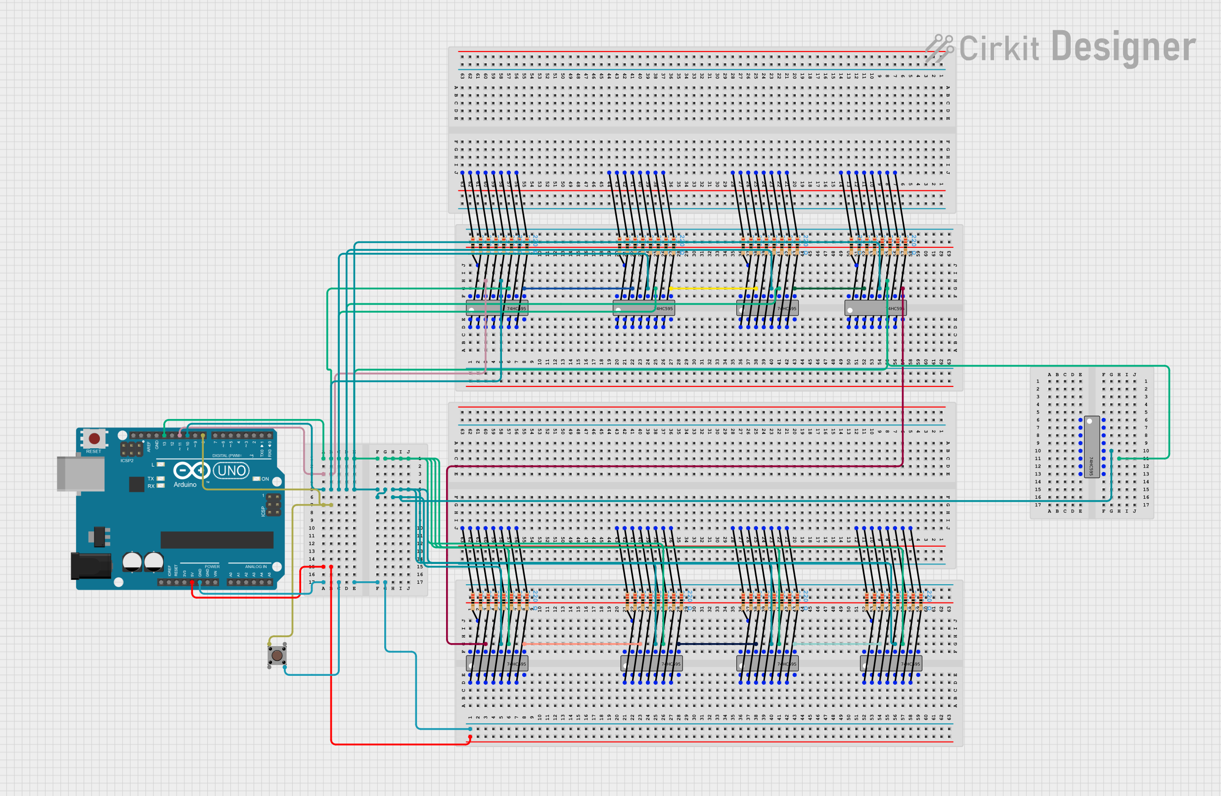
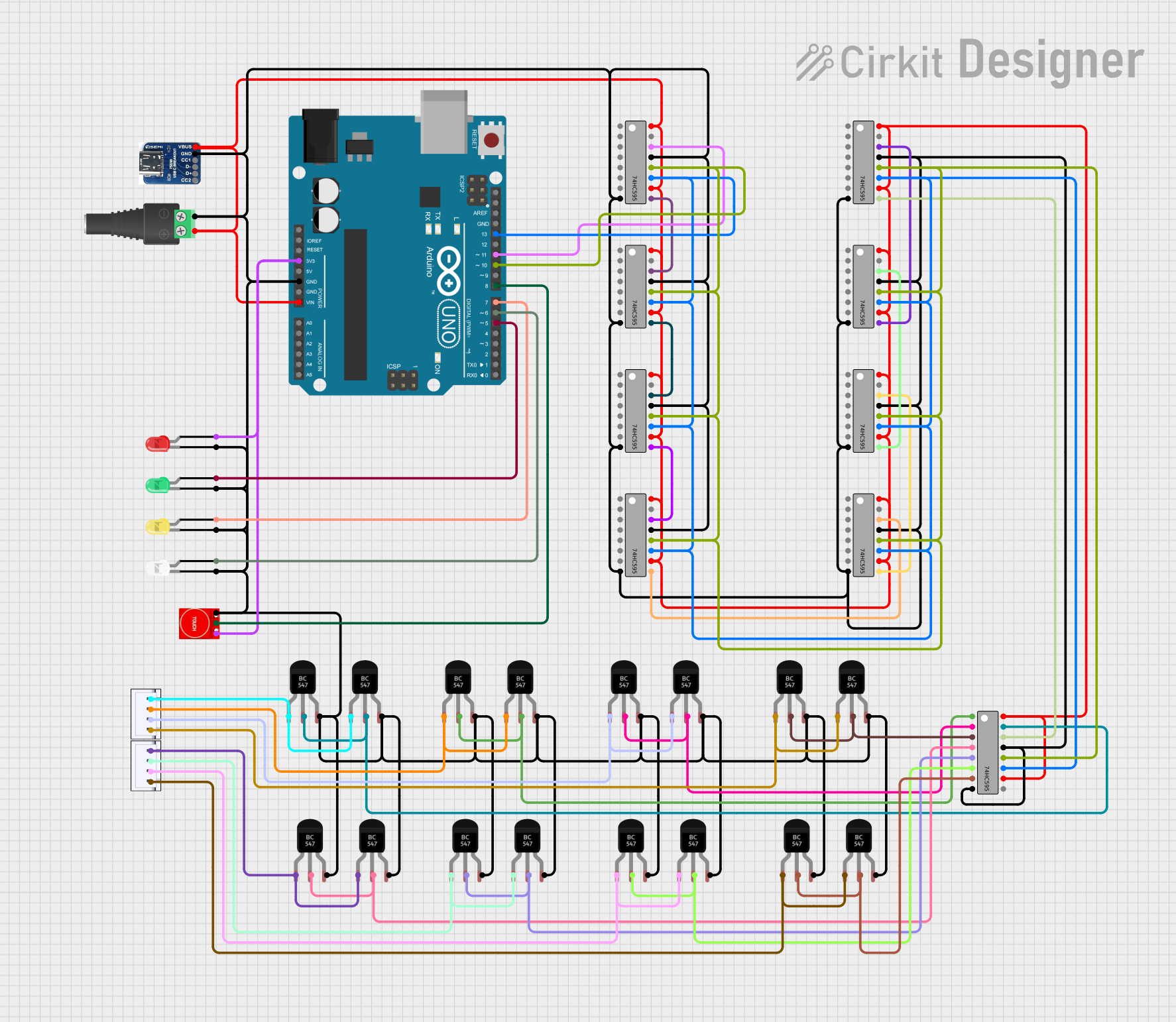

Explore Projects Built with 74HC21
Technical Specifications
Key Technical Details
- Logic Type: AND Gate
- Number of Gates: 2
- Number of Inputs per Gate: 4
- Supply Voltage (Vcc): 2V to 6V
- High-Level Input Voltage (Vih): Minimum 3.15V (for Vcc = 4.5V)
- Low-Level Input Voltage (Vil): Maximum 1.35V (for Vcc = 4.5V)
- Output Current: ±5.2 mA (maximum)
- Propagation Delay Time: Approximately 15 ns (for Vcc = 4.5V)
- Operating Temperature Range: -55°C to +125°C
Pin Configuration and Descriptions
| Pin Number | Description |
|---|---|
| 1 | Y1 Output |
| 2 | A1 Input |
| 3 | B1 Input |
| 4 | C1 Input |
| 5 | D1 Input |
| 6 | GND (Ground) |
| 7 | Y2 Output |
| 8 | A2 Input |
| 9 | B2 Input |
| 10 | C2 Input |
| 11 | D2 Input |
| 12 | Vcc (Supply Voltage) |
| 13 | NC (No Connection) |
| 14 | NC (No Connection) |
Usage Instructions
How to Use the 74HC21 in a Circuit
Power Supply: Connect the Vcc pin (pin 12) to a positive supply voltage between 2V and 6V. Connect the GND pin (pin 6) to the ground of the circuit.
Inputs: Apply logic signals to the A, B, C, and D inputs of the gates. Ensure that the input voltage levels are compatible with the Vih and Vil specifications.
Outputs: The Y outputs (pins 1 and 7) will be HIGH only when all corresponding A, B, C, and D inputs for that gate are HIGH. Otherwise, the output will be LOW.
Unused Inputs: If any inputs are not used, they should be tied to a logic LOW level to ensure predictable operation.
Important Considerations and Best Practices
Decoupling Capacitors: Place a 0.1 µF ceramic decoupling capacitor close to the Vcc pin to filter out noise and stabilize the power supply.
Input Protection: Avoid applying voltages to the inputs that exceed the supply voltage or go below ground to prevent damage to the IC.
Output Loading: Do not exceed the maximum output current specifications to avoid damaging the IC and ensure proper operation.
Troubleshooting and FAQs
Common Issues
Outputs Not Behaving as Expected: Verify that all inputs are at the correct logic levels. Check for proper power supply voltage and ensure that the IC is not damaged.
IC Getting Hot: Ensure that the supply voltage is within the specified range and that the output current is not exceeding the maximum ratings.
Solutions and Tips for Troubleshooting
Check Connections: Double-check all wiring and solder joints for any shorts or opens that could affect the operation.
Measure Voltages: Use a multimeter to measure the supply voltage and the input/output voltages to ensure they are within specified limits.
Replace IC: If the IC is suspected to be faulty, replace it with a new one and retest the circuit.
FAQs
Q: Can I use the 74HC21 with a 3.3V logic system? A: Yes, the 74HC21 can operate at 3.3V, but ensure that all input signals are also at 3.3V logic levels.
Q: What happens if I leave some inputs unconnected? A: Unconnected inputs can pick up noise and cause unpredictable behavior. It is best to tie unused inputs to a known logic level.
Q: Is the 74HC21 compatible with TTL logic? A: The 74HC21 is CMOS technology and has different voltage levels compared to TTL. However, it can often interface with TTL logic if the voltage levels are taken into consideration.
Example Code for Arduino UNO
The following example demonstrates how to use the 74HC21 with an Arduino UNO to perform a logical AND operation with four input switches.
// Define the input pins connected to the 74HC21
const int inputA = 2;
const int inputB = 3;
const int inputC = 4;
const int inputD = 5;

// Define the output pin connected to the 74HC21
const int outputY = 6;

void setup() {
  // Set the input pins as INPUT_PULLUP to use the internal pull-up resistors
  pinMode(inputA, INPUT_PULLUP);
  pinMode(inputB, INPUT_PULLUP);
  pinMode(inputC, INPUT_PULLUP);
  pinMode(inputD, INPUT_PULLUP);

  // Set the output pin as an output
  pinMode(outputY, OUTPUT);
}

void loop() {
  // Read the state of the input pins
  bool stateA = !digitalRead(inputA); // Invert because INPUT_PULLUP makes the button active-low
  bool stateB = !digitalRead(inputB);
  bool stateC = !digitalRead(inputC);
  bool stateD = !digitalRead(inputD);

  // Perform the AND operation and set the output pin
  bool andResult = stateA && stateB && stateC && stateD;
  digitalWrite(outputY, andResult);

  // Add a small delay to debounce the switches
  delay(50);
}
In this example, the Arduino reads the state of four input switches connected to the inputs of the 74HC21 and sets an LED connected to the output pin based on the result of the AND operation. The INPUT_PULLUP configuration is used to simplify the circuit by avoiding the need for external pull-up resistors.