How to Use 74192: Examples, Pinouts, and Specs
Introduction
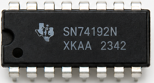
The 74192 is a synchronous 4-bit binary up/down counter with additional features such as parallel load capability and an active-low reset. It is widely used in digital circuits for counting applications, including frequency division, digital clocks, and event counting. The 74192 can count both upwards and downwards, making it versatile for various applications requiring bidirectional counting.
Explore Projects Built with 74192


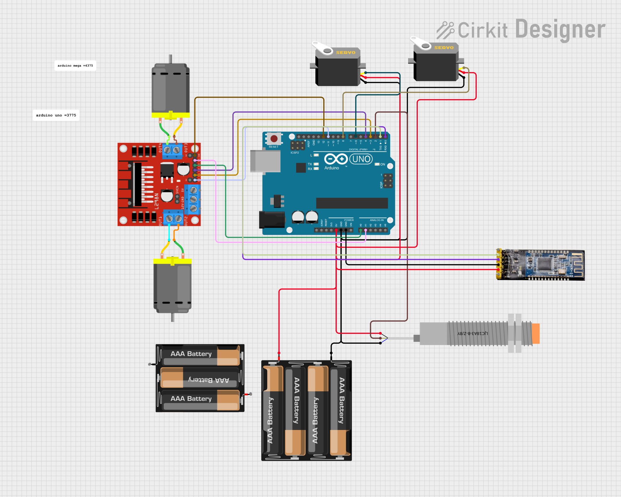
Explore Projects Built with 74192
Common Applications:
- Digital clocks and timers
- Frequency counters
- Event counters
- Programmable dividers
- Sequential logic circuits
Technical Specifications
The 74192 is a TTL (Transistor-Transistor Logic) IC designed for reliable and precise counting operations. Below are its key technical specifications:
| Parameter | Value |
|---|---|
| Supply Voltage (Vcc) | 4.75V to 5.25V |
| Input High Voltage | 2.0V (minimum) |
| Input Low Voltage | 0.8V (maximum) |
| Output High Voltage | 2.4V (minimum) |
| Output Low Voltage | 0.4V (maximum) |
| Maximum Clock Frequency | 32 MHz |
| Propagation Delay | 25 ns (typical) |
| Power Dissipation | 90 mW (typical) |
| Operating Temperature | 0°C to 70°C |
Pin Configuration and Descriptions
The 74192 IC comes in a 16-pin Dual In-line Package (DIP). Below is the pinout and description:
| Pin Number | Pin Name | Description |
|---|---|---|
| 1 | MR | Master Reset (Active Low) - Resets the counter to 0 |
| 2 | CPD | Count Down Clock Input - Decrements the counter on the falling edge |
| 3 | PL | Parallel Load (Active Low) - Loads data from inputs D0-D3 |
| 4 | Q3 | Output Bit 3 (Most Significant Bit) |
| 5 | Q2 | Output Bit 2 |
| 6 | Q1 | Output Bit 1 |
| 7 | Q0 | Output Bit 0 (Least Significant Bit) |
| 8 | GND | Ground |
| 9 | BORROW | Borrow Output - Indicates underflow during count down |
| 10 | CARRY | Carry Output - Indicates overflow during count up |
| 11 | CPU | Count Up Clock Input - Increments the counter on the falling edge |
| 12 | D0 | Parallel Data Input Bit 0 |
| 13 | D1 | Parallel Data Input Bit 1 |
| 14 | D2 | Parallel Data Input Bit 2 |
| 15 | D3 | Parallel Data Input Bit 3 |
| 16 | Vcc | Positive Supply Voltage |
Usage Instructions
How to Use the 74192 in a Circuit
- Power Supply: Connect pin 16 (Vcc) to a +5V power supply and pin 8 (GND) to ground.
- Clock Inputs: Use the
CPU(pin 11) for counting up andCPD(pin 2) for counting down. Ensure only one clock input is active at a time to avoid conflicts. - Reset: To reset the counter to 0, apply a low signal to the
MR(pin 1). - Parallel Load: To load a specific value into the counter, apply the desired binary value to
D0-D3(pins 12-15) and pull thePL(pin 3) low momentarily. - Outputs: The counter value is available on
Q0-Q3(pins 4-7). These outputs can be connected to LEDs, 7-segment displays, or other digital circuits. - Carry and Borrow: Use the
CARRY(pin 10) andBORROW(pin 9) outputs for cascading multiple counters or detecting overflow/underflow conditions.
Example Circuit with Arduino UNO
The 74192 can be interfaced with an Arduino UNO for control and monitoring. Below is an example code snippet to increment the counter using the CPU pin.
// Define pin connections
const int CPU = 2;  // Arduino pin connected to 74192 CPU (Count Up)
const int MR = 3;   // Arduino pin connected to 74192 MR (Master Reset)
const int Q0 = 4;   // Arduino pin connected to 74192 Q0
const int Q1 = 5;   // Arduino pin connected to 74192 Q1
const int Q2 = 6;   // Arduino pin connected to 74192 Q2
const int Q3 = 7;   // Arduino pin connected to 74192 Q3

void setup() {
  // Set pin modes
  pinMode(CPU, OUTPUT);
  pinMode(MR, OUTPUT);
  pinMode(Q0, INPUT);
  pinMode(Q1, INPUT);
  pinMode(Q2, INPUT);
  pinMode(Q3, INPUT);

  // Reset the counter
  digitalWrite(MR, LOW);  // Activate reset
  delay(10);              // Wait for reset to take effect
  digitalWrite(MR, HIGH); // Deactivate reset
}

void loop() {
  // Generate a clock pulse to increment the counter
  digitalWrite(CPU, LOW);  // Falling edge
  delay(10);               // Short delay
  digitalWrite(CPU, HIGH); // Rising edge
  delay(10);               // Short delay

  // Read and print the counter value
  int count = digitalRead(Q0) |
              (digitalRead(Q1) << 1) |
              (digitalRead(Q2) << 2) |
              (digitalRead(Q3) << 3);
  Serial.println(count);   // Print the counter value to the Serial Monitor
  delay(500);              // Wait before the next increment
}
Important Considerations:
- Ensure proper debounce mechanisms for clock inputs to avoid unintended counts.
- Avoid simultaneous activation of
CPUandCPDto prevent erratic behavior. - Use pull-up or pull-down resistors on unused inputs to prevent floating states.
Troubleshooting and FAQs
Common Issues and Solutions
Counter Not Incrementing or Decrementing:
- Ensure the clock signal is properly connected and toggling.
- Verify that the
MRpin is not held low, as this will keep the counter in reset.
Incorrect Output Values:
- Check the connections to
D0-D3andQ0-Q3for loose or incorrect wiring. - Ensure the power supply voltage is within the specified range.
- Check the connections to
Counter Resets Unexpectedly:
- Verify that the
MRpin is not being accidentally triggered. - Check for noise or glitches on the reset line.
- Verify that the
Carry/Borrow Outputs Not Functioning:
- Ensure the counter has reached its maximum or minimum value for these outputs to activate.
- Verify proper cascading connections if using multiple counters.
FAQs
Q1: Can the 74192 count in hexadecimal?
A1: No, the 74192 is a 4-bit binary counter and counts in binary (0-15). For hexadecimal representation, you can interpret the binary outputs accordingly.
Q2: How do I cascade multiple 74192 ICs?
A2: Connect the CARRY output of the lower-order counter to the CPU input of the higher-order counter for counting up. Similarly, connect the BORROW output to the CPD input for counting down.
Q3: Can I use the 74192 with a 3.3V power supply?
A3: No, the 74192 is designed for a 5V TTL logic level. Using a 3.3V supply may result in unreliable operation.