Cirkit Designer Logo
Cirkit Designer
Your all-in-one circuit design IDE
Home / 
Component Documentation

How to Use Step Up Boost Power Converter, Adjustable Voltage Regulator: Examples, Pinouts, and Specs

Image of Step Up Boost Power Converter, Adjustable Voltage Regulator
Cirkit Designer LogoDesign with Step Up Boost Power Converter, Adjustable Voltage Regulator in Cirkit Designer

Introduction

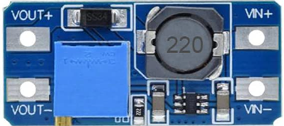
The Youmile Step Up Boost Power Converter is a versatile and efficient adjustable voltage regulator designed to step up a lower input voltage to a higher, stable output voltage. This component is widely used in applications requiring a regulated power supply, such as powering microcontrollers, LED strips, battery-powered devices, and portable electronics.

Its compact design and adjustable output voltage make it ideal for hobbyists, engineers, and DIY enthusiasts working on projects that require precise voltage regulation.

Explore Projects Built with Step Up Boost Power Converter, Adjustable Voltage Regulator

Use Cirkit Designer to design, explore, and prototype these projects online. Some projects support real-time simulation. Click "Open Project" to start designing instantly!
Battery-Powered Adjustable Voltage Regulator with Power Jack
Image of batteries : A project utilizing Step Up Boost Power Converter, Adjustable Voltage Regulator in a practical application
This circuit takes a 7V input from a battery and uses a Step Up Boost Power Converter to increase the voltage to a higher, adjustable level. The boosted voltage is then supplied to a power jack for external use.
Cirkit Designer LogoOpen Project in Cirkit Designer
Multi-Stage Voltage Regulation and Indicator LED Circuit
Image of Subramanyak_Power_Circuit: A project utilizing Step Up Boost Power Converter, Adjustable Voltage Regulator in a practical application
This circuit is designed for power management, featuring buck and boost converters for voltage adjustment, and linear regulators for stable voltage output. It includes LEDs for status indication, and terminal blocks for external connections.
Cirkit Designer LogoOpen Project in Cirkit Designer
Battery-Powered Adjustable Voltage Regulator with Li-ion 18650 Batteries and BMS
Image of mini ups: A project utilizing Step Up Boost Power Converter, Adjustable Voltage Regulator in a practical application
This circuit is a power management system that uses four Li-ion 18650 batteries connected to a 2S 30A BMS for battery management and protection. The system includes step-up and step-down voltage regulators to provide adjustable output voltages, controlled by a rocker switch, and multiple DC jacks for power input and output.
Cirkit Designer LogoOpen Project in Cirkit Designer
Battery-Powered 18650 Li-ion Charger with USB Output and Adjustable Voltage Regulator
Image of Breadboard: A project utilizing Step Up Boost Power Converter, Adjustable Voltage Regulator in a practical application
This circuit is a battery management and power supply system that uses three 3.7V batteries connected to a 3S 10A Li-ion 18650 Charger Protection Board Module for balanced charging and protection. The system includes a TP4056 Battery Charging Protection Module for additional charging safety, a Step Up Boost Power Converter to regulate and boost the voltage, and a USB regulator to provide a stable 5V output, controlled by a push switch.
Cirkit Designer LogoOpen Project in Cirkit Designer

Explore Projects Built with Step Up Boost Power Converter, Adjustable Voltage Regulator

Use Cirkit Designer to design, explore, and prototype these projects online. Some projects support real-time simulation. Click "Open Project" to start designing instantly!
Image of batteries : A project utilizing Step Up Boost Power Converter, Adjustable Voltage Regulator in a practical application
Battery-Powered Adjustable Voltage Regulator with Power Jack
This circuit takes a 7V input from a battery and uses a Step Up Boost Power Converter to increase the voltage to a higher, adjustable level. The boosted voltage is then supplied to a power jack for external use.
Cirkit Designer LogoOpen Project in Cirkit Designer
Image of Subramanyak_Power_Circuit: A project utilizing Step Up Boost Power Converter, Adjustable Voltage Regulator in a practical application
Multi-Stage Voltage Regulation and Indicator LED Circuit
This circuit is designed for power management, featuring buck and boost converters for voltage adjustment, and linear regulators for stable voltage output. It includes LEDs for status indication, and terminal blocks for external connections.
Cirkit Designer LogoOpen Project in Cirkit Designer
Image of mini ups: A project utilizing Step Up Boost Power Converter, Adjustable Voltage Regulator in a practical application
Battery-Powered Adjustable Voltage Regulator with Li-ion 18650 Batteries and BMS
This circuit is a power management system that uses four Li-ion 18650 batteries connected to a 2S 30A BMS for battery management and protection. The system includes step-up and step-down voltage regulators to provide adjustable output voltages, controlled by a rocker switch, and multiple DC jacks for power input and output.
Cirkit Designer LogoOpen Project in Cirkit Designer
Image of Breadboard: A project utilizing Step Up Boost Power Converter, Adjustable Voltage Regulator in a practical application
Battery-Powered 18650 Li-ion Charger with USB Output and Adjustable Voltage Regulator
This circuit is a battery management and power supply system that uses three 3.7V batteries connected to a 3S 10A Li-ion 18650 Charger Protection Board Module for balanced charging and protection. The system includes a TP4056 Battery Charging Protection Module for additional charging safety, a Step Up Boost Power Converter to regulate and boost the voltage, and a USB regulator to provide a stable 5V output, controlled by a push switch.
Cirkit Designer LogoOpen Project in Cirkit Designer

Technical Specifications

  • Manufacturer: Youmile
  • Model: Step Up Boost Power Converter
  • Input Voltage Range: 3V to 35V DC
  • Output Voltage Range: 4V to 40V DC (adjustable via potentiometer)
  • Maximum Output Current: 3A (with proper heat dissipation)
  • Efficiency: Up to 92% (depending on input/output voltage and load)
  • Switching Frequency: 150 kHz
  • Dimensions: Approximately 43mm x 21mm x 14mm
  • Weight: ~10g

Pin Configuration and Descriptions

Pin Name Description
VIN+ Positive input voltage terminal (connect to the positive side of the power source).
VIN- Negative input voltage terminal (connect to the ground of the power source).
VOUT+ Positive output voltage terminal (connect to the positive side of the load).
VOUT- Negative output voltage terminal (connect to the ground of the load).

Usage Instructions

How to Use the Component in a Circuit

  1. Connect the Input Voltage:

    • Connect the VIN+ pin to the positive terminal of your power source.
    • Connect the VIN- pin to the ground terminal of your power source.
    • Ensure the input voltage is within the specified range (3V to 35V DC).
  2. Connect the Output Voltage:

    • Connect the VOUT+ pin to the positive terminal of your load.
    • Connect the VOUT- pin to the ground terminal of your load.
  3. Adjust the Output Voltage:

    • Use a small screwdriver to turn the onboard potentiometer.
    • Turn clockwise to increase the output voltage or counterclockwise to decrease it.
    • Use a multimeter to measure the output voltage while adjusting to ensure accuracy.
  4. Power On:

    • Once all connections are secure, power on the input source.
    • Verify the output voltage and ensure it matches the requirements of your load.

Important Considerations and Best Practices

  • Heat Dissipation: If the output current exceeds 2A, ensure proper heat dissipation by attaching a heatsink or using active cooling.
  • Input Voltage: The input voltage must always be lower than the desired output voltage for proper operation.
  • Polarity: Double-check the polarity of your connections to avoid damaging the module.
  • Load Requirements: Ensure the load does not exceed the maximum output current of 3A.

Example: Using with an Arduino UNO

The Step Up Boost Power Converter can be used to power an Arduino UNO from a lower voltage source, such as a 3.7V Li-ion battery. Below is an example setup:

  1. Connect the VIN+ and VIN- pins to the battery terminals.
  2. Adjust the output voltage to 5V using the potentiometer.
  3. Connect the VOUT+ pin to the Arduino's 5V pin and the VOUT- pin to the Arduino's GND pin.

Here is a simple Arduino code example to blink an LED, powered by the boost converter:

// This code blinks an LED connected to pin 13 of the Arduino UNO.
// Ensure the boost converter is providing a stable 5V to the Arduino.

void setup() {
  pinMode(13, OUTPUT); // Set pin 13 as an output pin
}

void loop() {
  digitalWrite(13, HIGH); // Turn the LED on
  delay(1000);            // Wait for 1 second
  digitalWrite(13, LOW);  // Turn the LED off
  delay(1000);            // Wait for 1 second
}

Troubleshooting and FAQs

Common Issues and Solutions

  1. No Output Voltage:

    • Check all connections for proper polarity.
    • Verify that the input voltage is within the specified range.
    • Ensure the potentiometer is not turned too far counterclockwise (minimum output voltage).
  2. Overheating:

    • Reduce the load current if it exceeds 2A.
    • Attach a heatsink or use active cooling to dissipate heat.
  3. Fluctuating Output Voltage:

    • Ensure the input voltage is stable and not dropping under load.
    • Check for loose connections or damaged wires.
  4. Output Voltage Not Adjustable:

    • Verify that the potentiometer is functioning correctly.
    • Ensure the input voltage is lower than the desired output voltage.

FAQs

  • Q: Can this module step down voltage?
    A: No, this is a step-up (boost) converter and cannot step down voltage. Use a buck converter for step-down applications.

  • Q: Can I use this module with a solar panel?
    A: Yes, as long as the solar panel's output voltage is within the input range (3V to 35V DC).

  • Q: Is the module protected against reverse polarity?
    A: No, the module does not have reverse polarity protection. Always double-check your connections.

  • Q: Can I use this module to charge a battery?
    A: While possible, it is not recommended unless you have additional circuitry to manage the charging process safely.

By following this documentation, you can effectively integrate the Youmile Step Up Boost Power Converter into your projects and ensure reliable performance.