How to Use A4988 Stepper Motor Driver (Red): Examples, Pinouts, and Specs
Introduction
The A4988 Stepper Motor Driver is a compact module capable of driving bipolar stepper motors. The red variant of the A4988 by Photect is designed to offer a simple and efficient solution for controlling stepper motors in 3D printers, CNC machines, and other precision motion control applications.
Explore Projects Built with A4988 Stepper Motor Driver (Red)

Explore Projects Built with A4988 Stepper Motor Driver (Red)
Common Applications and Use Cases
- 3D Printers
- CNC Machines
- Robotics
- Precise position control systems
Technical Specifications
Key Technical Details
- Logic Voltage (VDD): 3.3 - 5.5 V
- Motor Supply Voltage (VM): 8 - 35 V
- Output Current (Max): 2 A (with proper heat sinking)
- Microstep Resolutions: Full, 1/2, 1/4, 1/8, 1/16
- Thermal Shutdown Circuitry: Yes
- Under-voltage Lockout: Yes
- Crossover-Current Protection: Yes
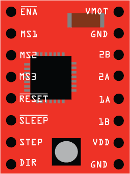
Pin Configuration and Descriptions
| Pin Number | Name | Description |
|---|---|---|
| 1 | VMOT | Motor supply voltage (8-35 V) |
| 2 | GND | Ground for motor power (0 V) |
| 3 | 2B | Motor connection B2 |
| 4 | 2A | Motor connection A2 |
| 5 | 1A | Motor connection A1 |
| 6 | 1B | Motor connection B1 |
| 7 | VDD | Logic supply voltage (3.3-5.5 V) |
| 8 | GND | Ground for logic power (0 V) |
| 9 | RESET | Resets the translator to a predefined Home state |
| 10 | SLP | Sleep mode input |
| 11 | STEP | Step input |
| 12 | DIR | Direction input |
| 13 | MS1 | Microstep selection 1 |
| 14 | MS2 | Microstep selection 2 |
| 15 | MS3 | Microstep selection 3 |
| 16 | EN | Enable motor output |
Usage Instructions
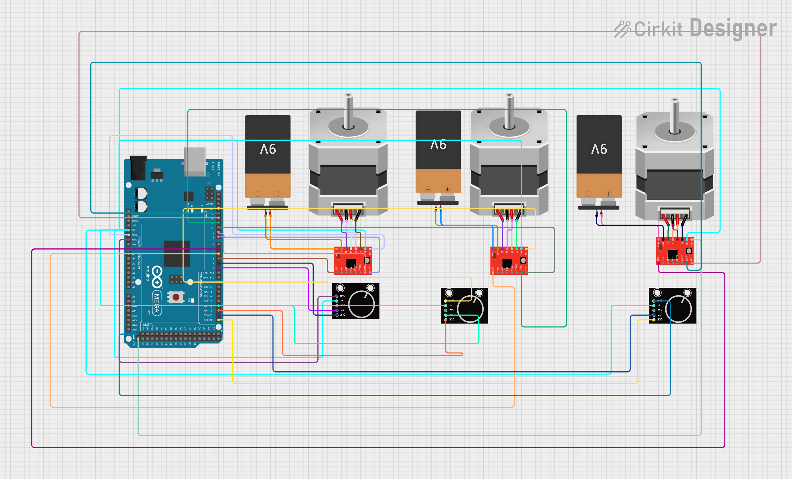
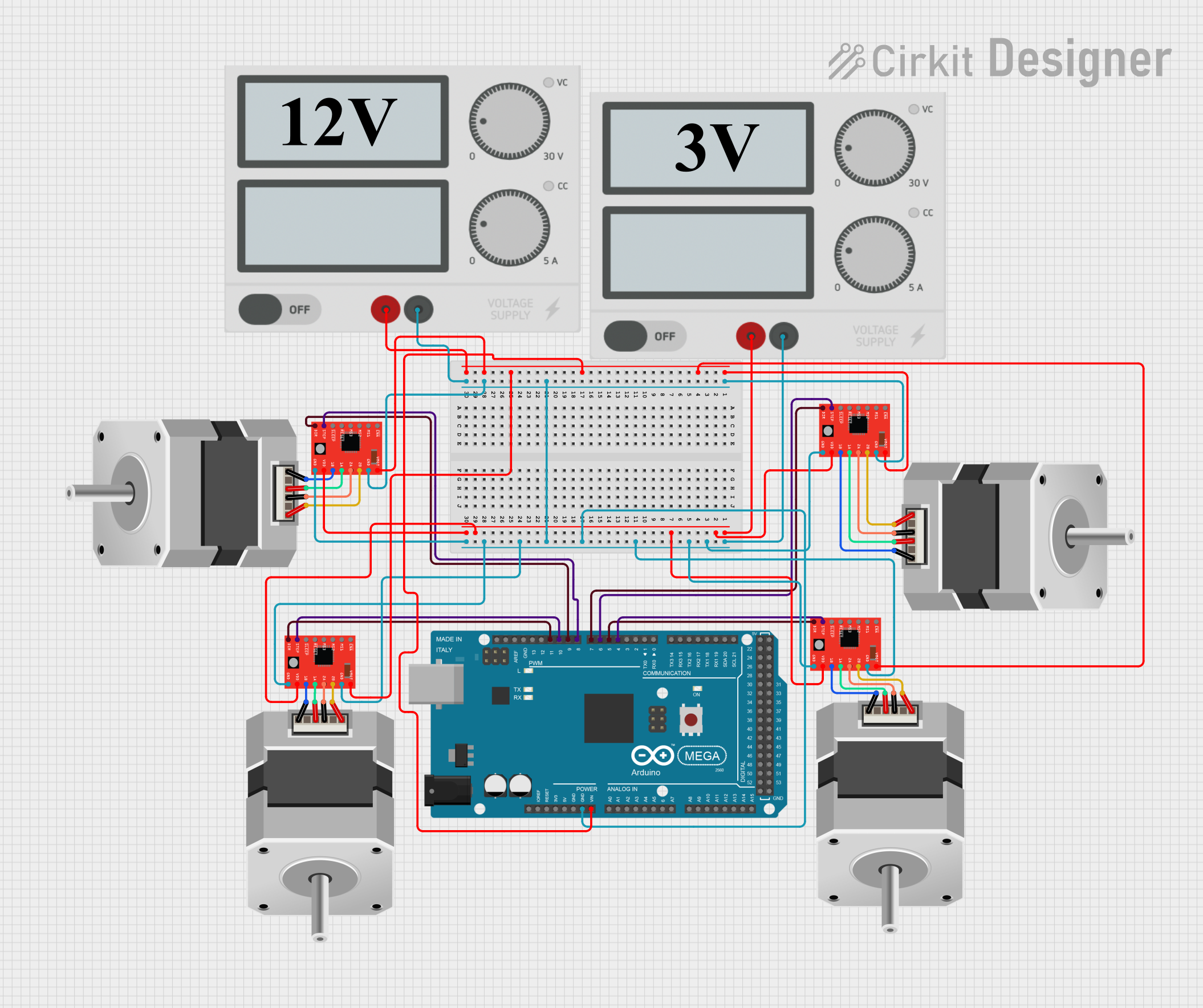
How to Use the Component in a Circuit
Power Connections: Connect VMOT to a suitable power supply (8-35 V) and VDD to a 3.3-5.5 V logic supply. Ensure both grounds are connected to a common ground.
Motor Connections: Connect the stepper motor coils to the 1A, 1B, 2A, and 2B pins.
Control Inputs: Connect the STEP and DIR pins to the digital outputs of a microcontroller to control the stepping and direction.
Microstep Configuration: Set the MS1, MS2, and MS3 pins to logic high or low according to the desired microstepping resolution.
Enable and Sleep Modes: Use the EN and SLP pins to enable or disable the motor output and to put the driver into sleep mode, respectively.
Important Considerations and Best Practices
- Always use a decoupling capacitor (typically 100 µF) across the VMOT and GND pins to stabilize the power supply.
- Avoid disconnecting the motor while the driver is powered to prevent damage.
- Use heat sinks and active cooling if operating near the maximum current rating.
- Ensure that the current limiting is set correctly to prevent overheating and damage to the motor.
Troubleshooting and FAQs
Common Issues
- Motor not moving: Check power supply, wiring, and ensure that the current limit is set correctly.
- Overheating: Ensure proper heat sinking and airflow. Adjust the current limit if necessary.
- Erratic movement: Verify microstep settings and input signal integrity.
Solutions and Tips for Troubleshooting
- Double-check all connections and solder joints.
- Use an oscilloscope to check the STEP and DIR signal integrity.
- Ensure that the firmware is configured correctly for the A4988 driver.
FAQs
Q: Can I drive a 5V stepper motor with this driver? A: Yes, as long as the motor's required voltage and current are within the driver's specifications.
Q: How do I set the current limit? A: Adjust the potentiometer on the board while measuring the voltage on the REF pin or by following the manufacturer's guidelines.
Q: What is the purpose of the microstep pins (MS1, MS2, MS3)? A: These pins allow you to select the microstep resolution for smoother and more precise motor control.
Example Code for Arduino UNO
// Define the connections to the A4988
const int dirPin = 2;  // DIR pin connected to digital pin 2
const int stepPin = 3; // STEP pin connected to digital pin 3

void setup() {
  // Set the pin modes
  pinMode(dirPin, OUTPUT);
  pinMode(stepPin, OUTPUT);
}

void loop() {
  // Set the spinning direction clockwise
  digitalWrite(dirPin, HIGH);

  // Spin the stepper motor 1 revolution slowly
  for (int i = 0; i < 200; i++) {
    // These four lines result in 1 step:
    digitalWrite(stepPin, HIGH);
    delayMicroseconds(2000);
    digitalWrite(stepPin, LOW);
    delayMicroseconds(2000);
  }

  delay(1000); // Wait 1 second

  // Set the spinning direction counterclockwise
  digitalWrite(dirPin, LOW);

  // Spin the stepper motor 1 revolution quickly
  for (int i = 0; i < 200; i++) {
    // These four lines result in 1 step:
    digitalWrite(stepPin, HIGH);
    delayMicroseconds(1000);
    digitalWrite(stepPin, LOW);
    delayMicroseconds(1000);
  }

  delay(1000); // Wait 1 second
}
Note: The above code assumes that the A4988 is configured for full-step mode. Adjust the delay for different speeds and modify the loop count for the desired number of steps. Ensure that the current limit is set correctly before running the motor.