How to Use 3.3v LDO AP2112K-3.3: Examples, Pinouts, and Specs
Introduction
The AP2112K-3.3 is a low dropout (LDO) linear voltage regulator designed to provide a stable 3.3V output with high efficiency and low noise. It is ideal for powering sensitive electronic components, such as microcontrollers, sensors, and communication modules, in compact and portable devices. The AP2112K-3.3 is equipped with features like overcurrent protection and thermal shutdown, ensuring reliable operation in various applications.
Explore Projects Built with 3.3v LDO AP2112K-3.3


Explore Projects Built with 3.3v LDO AP2112K-3.3
Common Applications and Use Cases
- Powering microcontrollers (e.g., Arduino, ESP32, Raspberry Pi peripherals)
- Voltage regulation for sensors and communication modules
- Battery-powered devices
- Portable electronics
- Low-noise analog circuits
Technical Specifications
Key Technical Details
- Input Voltage Range: 2.5V to 6.0V
- Output Voltage: 3.3V (fixed)
- Output Current: Up to 600mA
- Dropout Voltage: 0.5V at 600mA
- Quiescent Current: 55µA (typical)
- Output Voltage Accuracy: ±1%
- Protection Features: Overcurrent protection, thermal shutdown
- Operating Temperature Range: -40°C to +85°C
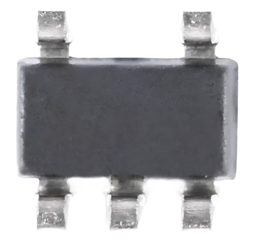
- Package Type: SOT-23-5
Pin Configuration and Descriptions
The AP2112K-3.3 is typically available in a 5-pin SOT-23 package. Below is the pinout and description:
| Pin Number | Pin Name | Description |
|---|---|---|
| 1 | GND | Ground pin |
| 2 | VIN | Input voltage pin (2.5V to 6.0V) |
| 3 | EN | Enable pin (active high, logic high to enable) |
| 4 | NC | No connection (leave unconnected or grounded) |
| 5 | VOUT | Regulated 3.3V output pin |
Usage Instructions
How to Use the AP2112K-3.3 in a Circuit
- Input Capacitor: Connect a 1µF ceramic capacitor close to the VIN pin to stabilize the input voltage.
- Output Capacitor: Connect a 1µF to 10µF ceramic capacitor close to the VOUT pin to ensure stable output voltage.
- Enable Pin: Tie the EN pin to VIN for always-on operation, or control it with a microcontroller or logic circuit for on/off functionality.
- Ground Connection: Ensure a low-impedance connection to the GND pin for proper operation.
- Load Current: Ensure the load current does not exceed 600mA to avoid triggering overcurrent protection.
Important Considerations and Best Practices
- Thermal Management: Ensure adequate heat dissipation, especially when operating near the maximum current limit.
- Dropout Voltage: Maintain an input voltage at least 0.5V higher than the output voltage for proper regulation.
- PCB Layout: Place input and output capacitors as close as possible to the regulator to minimize noise and improve stability.
- Enable Pin Usage: If not used, connect the EN pin to VIN to keep the regulator enabled.
Example: Using AP2112K-3.3 with Arduino UNO
The AP2112K-3.3 can be used to power an Arduino UNO or its peripherals. Below is an example circuit and Arduino code to control the EN pin.
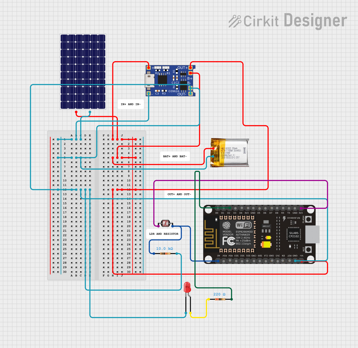
Circuit Diagram
- Connect the VIN pin to a 5V power source.
- Connect the VOUT pin to the 3.3V input of the Arduino peripheral.
- Use a digital pin on the Arduino to control the EN pin.
Arduino Code
// Example code to control the AP2112K-3.3 Enable pin using Arduino UNO

const int enablePin = 7; // Connect EN pin of AP2112K-3.3 to Arduino pin 7

void setup() {
  pinMode(enablePin, OUTPUT); // Set pin 7 as an output
  digitalWrite(enablePin, HIGH); // Enable the regulator (logic high)
}

void loop() {
  // Example: Toggle the regulator on and off every 5 seconds
  digitalWrite(enablePin, HIGH); // Enable the regulator
  delay(5000); // Wait for 5 seconds
  digitalWrite(enablePin, LOW); // Disable the regulator
  delay(5000); // Wait for 5 seconds
}
Troubleshooting and FAQs
Common Issues and Solutions
No Output Voltage:
- Ensure the EN pin is connected to VIN or a logic high signal.
- Verify that the input voltage is within the specified range (2.5V to 6.0V).
- Check for proper connections and soldering of the input and output capacitors.
Output Voltage is Unstable:
- Ensure the output capacitor is within the recommended range (1µF to 10µF).
- Use low-ESR ceramic capacitors for better stability.
- Verify that the input voltage is stable and free from excessive noise.
Regulator Overheating:
- Check if the load current exceeds 600mA.
- Ensure proper heat dissipation by using a PCB with adequate thermal management.
High Dropout Voltage:
- Verify that the input voltage is at least 0.5V higher than the output voltage.
FAQs
Q: Can I use the AP2112K-3.3 without the EN pin?
A: Yes, you can tie the EN pin directly to VIN for always-on operation.
Q: What type of capacitors should I use?
A: Use ceramic capacitors with low ESR for both input and output. A 1µF capacitor is recommended for the input, and a 1µF to 10µF capacitor is recommended for the output.
Q: Is the AP2112K-3.3 suitable for battery-powered devices?
A: Yes, its low quiescent current (55µA typical) makes it ideal for battery-powered applications.
Q: What happens if the load current exceeds 600mA?
A: The regulator will activate overcurrent protection to prevent damage. Reduce the load to restore normal operation.