
How to Use PLC_FX3U: Examples, Pinouts, and Specs
 Design with PLC_FX3U in Cirkit Designer
Introduction
The PLC_FX3U is a programmable logic controller (PLC) developed by Mitsubishi Electric. It is designed for industrial automation and control applications, offering a modular architecture that allows for seamless expansion and integration with a wide range of input/output (I/O) modules. The PLC_FX3U supports advanced programming capabilities, making it suitable for complex control tasks in manufacturing, process automation, and other industrial environments.
Explore Projects Built with PLC_FX3U
 Open Project in Cirkit Designer
 Open Project in Cirkit Designer
 Open Project in Cirkit Designer
 Open Project in Cirkit Designer
Explore Projects Built with PLC_FX3U
Open Project in Cirkit DesignerOpen Project in Cirkit DesignerOpen Project in Cirkit DesignerOpen Project in Cirkit DesignerCommon Applications and Use Cases
- Factory automation and production line control
- Process monitoring and control in industries such as food, beverage, and pharmaceuticals
- Building automation systems (e.g., HVAC, lighting control)
- Motion control and robotics
- Data acquisition and communication with SCADA systems
Technical Specifications
Key Technical Details
| Parameter | Specification |
|---|---|
| Power Supply Voltage | 100-240V AC or 24V DC |
| Input Voltage Range | 24V DC (for digital inputs) |
| Output Type | Relay or transistor (depending on model) |
| Maximum I/O Points | Up to 384 points (with expansion modules) |
| Programming Language | Ladder Logic, Structured Text, Function Block |
| Communication Interfaces | RS-232, RS-485, Ethernet (with optional modules) |
| Memory Capacity | 64k steps (expandable with memory modules) |
| Operating Temperature | 0°C to 55°C |
| Dimensions (Base Unit) | Varies by model (e.g., 90mm x 90mm x 75mm) |
Pin Configuration and Descriptions
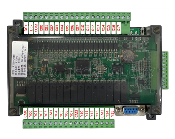
The PLC_FX3U base unit includes a variety of input and output terminals. Below is a general description of the pin configuration for a typical model:
Digital Input Terminals
| Pin Number | Label | Description |
|---|---|---|
| X0-X7 | Inputs | Digital input terminals (24V DC) |
| COM | Common | Common terminal for input signals |
Digital Output Terminals
| Pin Number | Label | Description |
|---|---|---|
| Y0-Y7 | Outputs | Digital output terminals |
| COM | Common | Common terminal for output signals |
Power Terminals
| Pin Number | Label | Description |
|---|---|---|
| L, N | AC Power | Connect to 100-240V AC power supply |
| +24V, 0V | DC Power | 24V DC power output for sensors |
Communication Ports
| Port | Description |
|---|---|
| RS-232 | Serial communication for programming/debugging |
| RS-485 | Serial communication for networking |
| Ethernet | Optional module for Ethernet communication |
Usage Instructions
How to Use the PLC_FX3U in a Circuit
- Power Connection: Connect the power supply to the L and N terminals for AC power or +24V and 0V for DC power. Ensure the power supply matches the voltage requirements of the PLC.
- Input Connections: Connect sensors or switches to the digital input terminals (X0-X7). Use the COM terminal as the common ground for the input devices.
- Output Connections: Connect actuators, relays, or other devices to the digital output terminals (Y0-Y7). Use the COM terminal as the common ground for the output devices.
- Programming: Use Mitsubishi's GX Works2 or GX Developer software to write and upload ladder logic or other supported programs to the PLC via the RS-232 or USB programming cable.
- Communication: For networking or data exchange, connect the RS-485 or Ethernet module (if available) to the appropriate communication port.
Important Considerations and Best Practices
- Always ensure the power supply voltage matches the PLC's specifications to avoid damage.
- Use proper shielding and grounding for communication cables to minimize electrical noise.
- When expanding the system with additional I/O modules, ensure compatibility with the base unit.
- Regularly back up the PLC program to avoid data loss during maintenance or power failures.
- Follow safety guidelines when working with high-voltage connections.
Example Code for Arduino Communication
The PLC_FX3U can communicate with an Arduino UNO via the RS-485 interface. Below is an example of Arduino code to send data to the PLC:
#include <ModbusMaster.h>

// Instantiate ModbusMaster object
ModbusMaster node;

void setup() {
  Serial.begin(9600); // Initialize serial communication
  node.begin(1, Serial); // Set Modbus slave ID to 1
}

void loop() {
  uint8_t result;

  // Write a single coil (e.g., turn on an output)
  result = node.writeSingleCoil(0x0001, 1); // Address 0x0001, set to ON
  if (result == node.ku8MBSuccess) {
    Serial.println("Coil written successfully!");
  } else {
    Serial.println("Failed to write coil.");
  }

  delay(1000); // Wait 1 second before next operation
}
Note: Ensure the RS-485 module is properly connected between the Arduino and the PLC. Match the baud rate and communication settings on both devices.
Troubleshooting and FAQs
Common Issues and Solutions
PLC Does Not Power On
- Cause: Incorrect power supply voltage or loose connections.
- Solution: Verify the power supply voltage and ensure all connections are secure.
Inputs Not Detected
- Cause: Faulty wiring or incorrect input voltage.
- Solution: Check the wiring and ensure the input devices provide 24V DC signals.
Outputs Not Activating
- Cause: Overloaded output or incorrect wiring.
- Solution: Verify the load connected to the output and ensure it is within the PLC's specifications.
Communication Failure
- Cause: Incorrect communication settings or faulty cables.
- Solution: Check the baud rate, parity, and other communication parameters. Replace damaged cables if necessary.
FAQs
Q: Can the PLC_FX3U be programmed using a USB cable?
A: Yes, with a USB-to-RS-232 adapter or a dedicated USB programming cable.Q: How many expansion modules can be added to the PLC_FX3U?
A: The PLC_FX3U supports up to 8 expansion modules, depending on the model and configuration.Q: Is the PLC_FX3U compatible with SCADA systems?
A: Yes, it can communicate with SCADA systems via RS-485, Ethernet, or other supported protocols.Q: What is the maximum memory capacity of the PLC_FX3U?
A: The base unit supports 64k steps, which can be expanded with additional memory modules.
By following this documentation, users can effectively utilize the PLC_FX3U for a wide range of automation and control applications.