Cirkit Designer Logo
Cirkit Designer
Your all-in-one circuit design IDE
Home / 
Component Documentation

How to Use Pushbutton START: Examples, Pinouts, and Specs

Image of Pushbutton START
Cirkit Designer LogoDesign with Pushbutton START in Cirkit Designer

Introduction

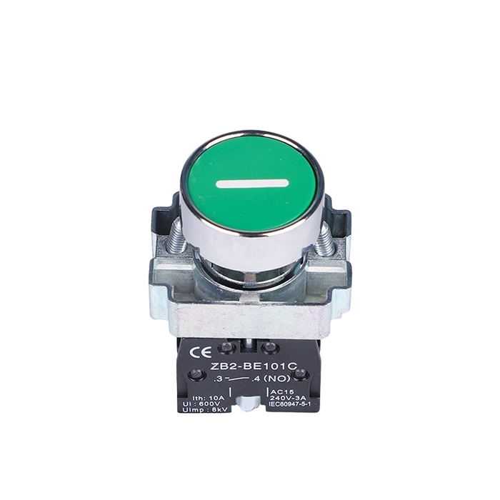
A pushbutton is a momentary switch that completes or breaks a circuit when pressed, allowing for user input in electronic devices. The Pushbutton START is a versatile and widely used component in electronics, enabling users to control circuits with a simple press. It is commonly found in applications such as user interfaces, control panels, and embedded systems.

Explore Projects Built with Pushbutton START

Use Cirkit Designer to design, explore, and prototype these projects online. Some projects support real-time simulation. Click "Open Project" to start designing instantly!
Pushbutton-Controlled Interface with 40-Pin Connector and UBS Power Supply
Image of connect 4: A project utilizing Pushbutton START in a practical application
This circuit consists of a 40-pin connector interfacing with four pushbuttons and a UBS power supply. The pushbuttons are used as inputs to the connector, which then relays the signals to other components or systems. The UBS power supply provides the necessary 24V power to the pushbuttons and the common ground for the circuit.
Cirkit Designer LogoOpen Project in Cirkit Designer
Arduino 101 Controlled DC Motor with Start/Stop Buttons and Pilot Lamp
Image of Skematik Motor: A project utilizing Pushbutton START in a practical application
This circuit is a motor control system using an Arduino 101, which interfaces with start and stop pushbuttons to control a DC motor via a PWM motor controller. A blue pilot lamp indicates the status, and the motor controller is powered through a socket and a DC power source.
Cirkit Designer LogoOpen Project in Cirkit Designer
Arduino Nano-Based Panic Button System with GPS and GSM Modules
Image of panic button .2\: A project utilizing Pushbutton START in a practical application
This circuit is designed as a panic button system featuring an Arduino Nano interfaced with a NEO6MV2 GPS module and three SIM800L GSM modules. It includes four pushbuttons, each assigned to trigger a call to a specific emergency service (hospital, fire department, police) or to send the GPS location. The system is powered by a lithium battery with a charging module, and it can send the GPS location to a predefined number or alongside an emergency call when the corresponding buttons are pressed simultaneously.
Cirkit Designer LogoOpen Project in Cirkit Designer
Battery-Powered LED Control with Pushbutton and Relay
Image of EXP.3 E: A project utilizing Pushbutton START in a practical application
This circuit uses a pushbutton to control a 5V relay, which in turn powers a red LED. The MAHIR 1.mini module provides the necessary 3.7V power supply, and the relay switches the LED on and off based on the pushbutton input.
Cirkit Designer LogoOpen Project in Cirkit Designer

Explore Projects Built with Pushbutton START

Use Cirkit Designer to design, explore, and prototype these projects online. Some projects support real-time simulation. Click "Open Project" to start designing instantly!
Image of connect 4: A project utilizing Pushbutton START in a practical application
Pushbutton-Controlled Interface with 40-Pin Connector and UBS Power Supply
This circuit consists of a 40-pin connector interfacing with four pushbuttons and a UBS power supply. The pushbuttons are used as inputs to the connector, which then relays the signals to other components or systems. The UBS power supply provides the necessary 24V power to the pushbuttons and the common ground for the circuit.
Cirkit Designer LogoOpen Project in Cirkit Designer
Image of Skematik Motor: A project utilizing Pushbutton START in a practical application
Arduino 101 Controlled DC Motor with Start/Stop Buttons and Pilot Lamp
This circuit is a motor control system using an Arduino 101, which interfaces with start and stop pushbuttons to control a DC motor via a PWM motor controller. A blue pilot lamp indicates the status, and the motor controller is powered through a socket and a DC power source.
Cirkit Designer LogoOpen Project in Cirkit Designer
Image of panic button .2\: A project utilizing Pushbutton START in a practical application
Arduino Nano-Based Panic Button System with GPS and GSM Modules
This circuit is designed as a panic button system featuring an Arduino Nano interfaced with a NEO6MV2 GPS module and three SIM800L GSM modules. It includes four pushbuttons, each assigned to trigger a call to a specific emergency service (hospital, fire department, police) or to send the GPS location. The system is powered by a lithium battery with a charging module, and it can send the GPS location to a predefined number or alongside an emergency call when the corresponding buttons are pressed simultaneously.
Cirkit Designer LogoOpen Project in Cirkit Designer
Image of EXP.3 E: A project utilizing Pushbutton START in a practical application
Battery-Powered LED Control with Pushbutton and Relay
This circuit uses a pushbutton to control a 5V relay, which in turn powers a red LED. The MAHIR 1.mini module provides the necessary 3.7V power supply, and the relay switches the LED on and off based on the pushbutton input.
Cirkit Designer LogoOpen Project in Cirkit Designer

Common Applications:

  • Powering on/off devices
  • Resetting microcontrollers or systems
  • User input for embedded systems
  • Triggering events in automation systems
  • Prototyping and testing circuits

Technical Specifications

Key Technical Details:

  • Type: Momentary pushbutton switch
  • Contact Configuration: Normally Open (NO) or Normally Closed (NC), depending on wiring
  • Operating Voltage: 3.3V to 24V (typical)
  • Current Rating: 50mA to 500mA (depending on model)
  • Contact Resistance: ≤ 50 mΩ
  • Insulation Resistance: ≥ 100 MΩ
  • Mechanical Life: 100,000 to 1,000,000 cycles
  • Mounting Style: Through-hole or panel mount
  • Debounce Time: Typically 5ms to 20ms

Pin Configuration and Descriptions:

The Pushbutton START typically has two or four pins, depending on the model. Below is the pin configuration for a standard 4-pin pushbutton:

Pin Number Label Description
1 NO Normally Open terminal
2 COM Common terminal
3 NC Normally Closed terminal (optional, not always present)
4 COM Common terminal (connected internally to Pin 2)

For a 2-pin pushbutton, the pins are simply connected to the NO and COM terminals.

Usage Instructions

How to Use the Pushbutton START in a Circuit:
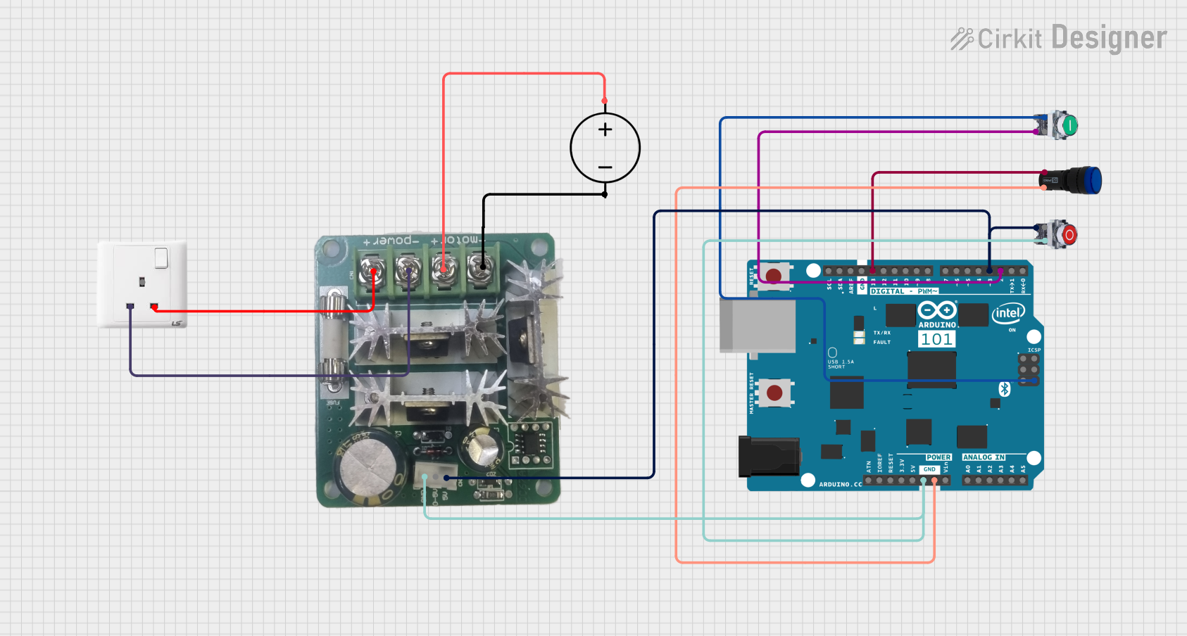
  1. Basic Connection:

    • Connect one terminal of the pushbutton to the positive voltage supply (e.g., 5V).
    • Connect the other terminal to the input pin of a microcontroller or circuit, with a pull-down resistor (typically 10kΩ) to ground. This ensures the input pin reads LOW when the button is not pressed.
  2. Debouncing:

    • Pushbuttons can produce noise or "bouncing" when pressed, causing multiple signals to be sent. Use a hardware debounce circuit (e.g., an RC filter) or software debounce logic to ensure stable operation.
  3. Interfacing with Arduino UNO:

    • The Pushbutton START can be easily connected to an Arduino UNO for user input. Below is an example code snippet:
// Example: Reading a pushbutton state with Arduino UNO
const int buttonPin = 2;  // Pin connected to the pushbutton
const int ledPin = 13;    // Pin connected to an onboard LED

void setup() {
  pinMode(buttonPin, INPUT_PULLUP); // Set button pin as input with internal pull-up
  pinMode(ledPin, OUTPUT);          // Set LED pin as output
}

void loop() {
  int buttonState = digitalRead(buttonPin); // Read the button state

  if (buttonState == LOW) { // Button pressed (LOW due to pull-up resistor)
    digitalWrite(ledPin, HIGH); // Turn on the LED
  } else {
    digitalWrite(ledPin, LOW);  // Turn off the LED
  }
}

Important Considerations:

  • Always use a pull-up or pull-down resistor to ensure stable readings.
  • Avoid exceeding the voltage and current ratings of the pushbutton.
  • For high-frequency switching, consider using a debounce circuit or software logic.
  • Ensure proper insulation and mounting to prevent accidental short circuits.

Troubleshooting and FAQs

Common Issues and Solutions:

  1. Button Not Responding:

    • Cause: Loose connections or incorrect wiring.
    • Solution: Check all connections and ensure the pushbutton is wired correctly.
  2. Multiple Signals When Pressed:

    • Cause: Button bouncing.
    • Solution: Implement a debounce circuit or software debounce logic.
  3. Microcontroller Not Detecting Button Press:

    • Cause: Missing pull-up or pull-down resistor.
    • Solution: Add a pull-up or pull-down resistor to stabilize the input pin.
  4. Button Feels Stuck or Unresponsive:

    • Cause: Mechanical wear or debris inside the button.
    • Solution: Clean the button or replace it if worn out.

FAQs:

  • Q: Can I use the Pushbutton START with a 3.3V system?

    • A: Yes, the pushbutton is compatible with 3.3V systems as long as the current rating is not exceeded.
  • Q: How do I debounce a pushbutton in software?

    • A: Use a delay or timing logic to ignore additional signals within a short time window (e.g., 10ms) after the first press.
  • Q: Can I use the pushbutton to control high-power devices?

    • A: No, the pushbutton is designed for low-power signals. Use a relay or transistor to control high-power devices.

By following this documentation, you can effectively integrate the Pushbutton START into your electronic projects and troubleshoot common issues with ease.