How to Use 12v wireless relay: Examples, Pinouts, and Specs
Introduction
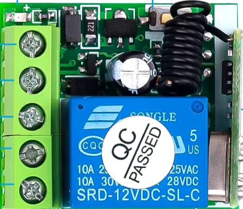
A 12V wireless relay is an electromechanical device that allows users to control high-power devices wirelessly. It operates at a 12V voltage level and can be triggered remotely, making it ideal for applications in home automation, industrial control, and remote power switching. The wireless relay module typically includes a relay (the switch), a wireless receiver, and an antenna.
Explore Projects Built with 12v wireless relay
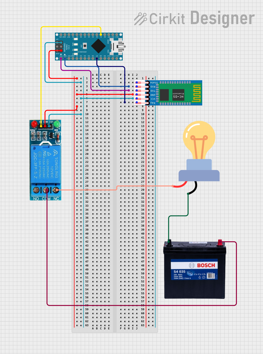

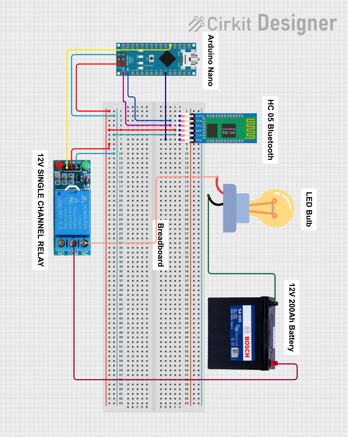
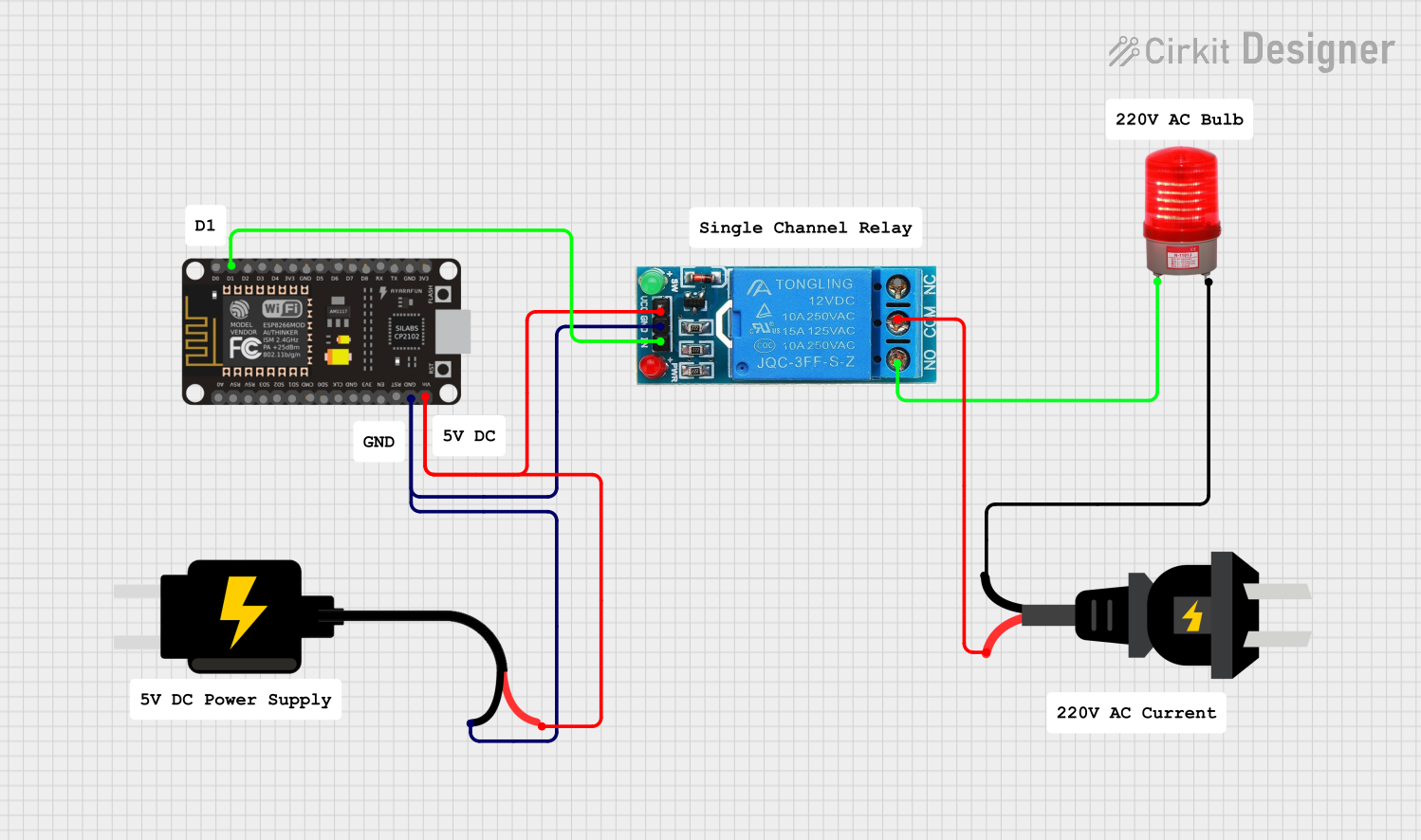
Explore Projects Built with 12v wireless relay
Common Applications and Use Cases
- Remote control of lights, fans, and other home appliances
- Automotive applications for controlling vehicle accessories
- Industrial machinery power control
- Remote activation of security systems
Technical Specifications
Key Technical Details
- Operating Voltage: 12V DC
- Relay Rating: Typically 10A at 250V AC or 30V DC
- Frequency: Commonly 433MHz for the wireless signal
- Range: Up to 100 meters (without obstacles)
Pin Configuration and Descriptions
| Pin Number | Description | Notes |
|---|---|---|
| 1 | VCC | Connect to 12V power supply |
| 2 | GND | Connect to ground |
| 3 | IN | Signal input from receiver |
| 4 | NO (Normally Open) | Relay switch open by default |
| 5 | COM (Common) | Common terminal for the switch |
| 6 | NC (Normally Closed) | Relay switch closed by default |
Usage Instructions
How to Use the Component in a Circuit
- Power Supply Connection: Connect the VCC pin to a 12V power supply and the GND pin to the ground.
- Load Connection: Connect the device you want to control to the NO or NC pin, and the other side of the device to the COM pin.
- Signal Input: Connect the IN pin to the wireless receiver output.
Important Considerations and Best Practices
- Ensure the load does not exceed the relay's maximum current and voltage rating.
- Use a diode across the relay coil to prevent back EMF when the relay deactivates.
- Place the antenna of the wireless receiver in a position with minimal obstructions for better range.
- Always disconnect power before making or altering connections.
Troubleshooting and FAQs
Common Issues
- Relay not activating: Check power supply and connections. Ensure the wireless signal is being received.
- Intermittent operation: Verify the antenna placement and check for sources of wireless interference.
- Overheating: Ensure the load does not exceed the relay's rating and check for any short circuits.
Solutions and Tips for Troubleshooting
- Test the relay independently with a direct 12V signal to ensure it is functioning.
- Replace the battery in the wireless transmitter if the range is significantly reduced.
- Use a multimeter to check for continuity and proper voltage levels in the circuit.
FAQs
Q: Can I use this relay with AC loads? A: Yes, as long as the load is within the relay's AC rating.
Q: How can I extend the wireless range? A: Minimize obstructions, use a higher gain antenna, or consider a signal repeater.
Q: Is it possible to control multiple relays with one transmitter? A: Yes, if the relays are designed to respond to the same signal or if the transmitter can send multiple signals.
Example Code for Arduino UNO
Below is an example code snippet for controlling a 12V wireless relay with an Arduino UNO. This assumes the relay's receiver is designed to accept a digital signal from the Arduino.
// Define the relay control pin
const int relayPin = 7;

void setup() {
  // Set the relay pin as an output
  pinMode(relayPin, OUTPUT);
}

void loop() {
  // Turn on the relay
  digitalWrite(relayPin, HIGH);
  delay(1000); // Wait for 1 second

  // Turn off the relay
  digitalWrite(relayPin, LOW);
  delay(1000); // Wait for 1 second
}
Note: This code is for illustration purposes. The actual implementation will depend on the specific wireless relay module and the wireless receiver's requirements. Always refer to the manufacturer's datasheet for precise operation details.