How to Use Photon 1: Examples, Pinouts, and Specs
Introduction
The Photon 1 is a compact, low-power microcontroller designed specifically for Internet of Things (IoT) applications. It features built-in Wi-Fi connectivity, making it ideal for projects that require wireless communication. With its simple programming interface and robust hardware, the Photon 1 enables rapid development and deployment of IoT solutions.
Explore Projects Built with Photon 1
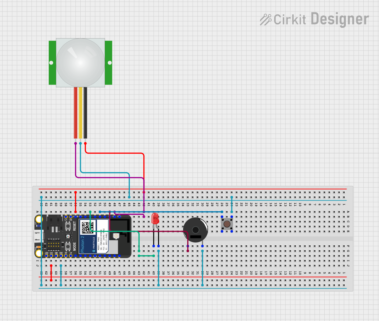
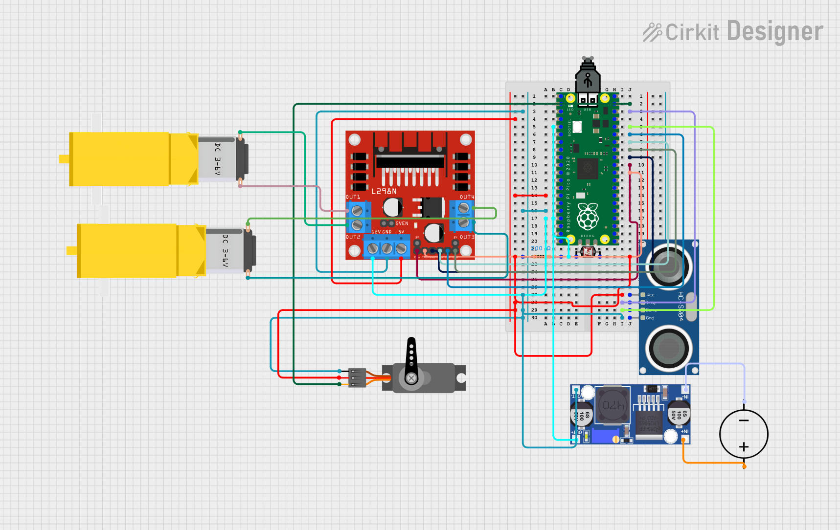
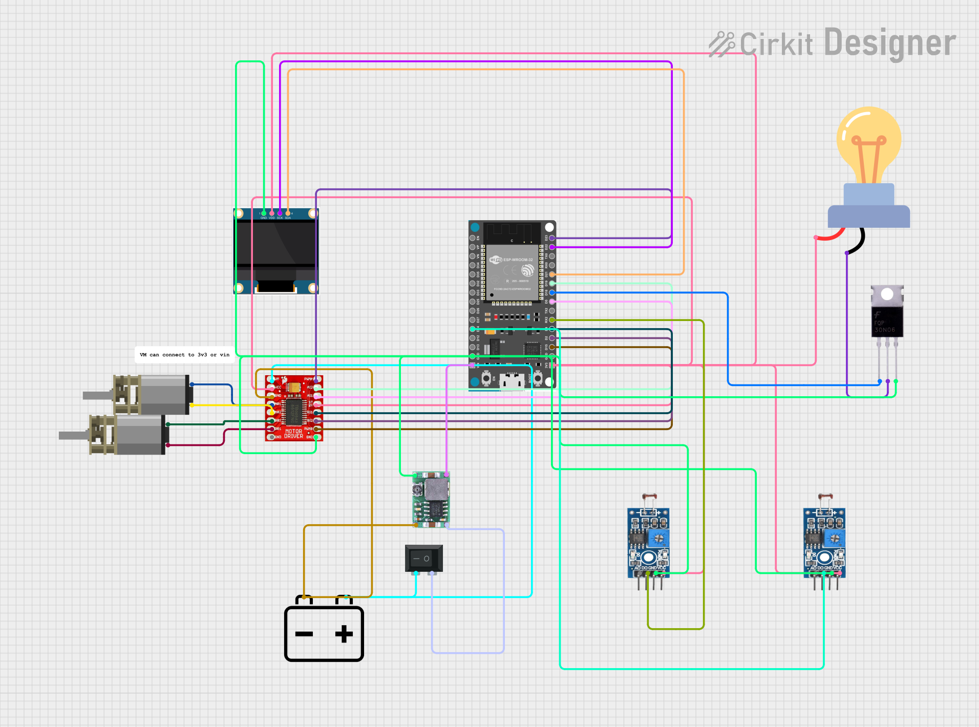
Explore Projects Built with Photon 1
Common Applications and Use Cases
- Smart home devices (e.g., connected lights, thermostats)
- Remote monitoring systems (e.g., temperature, humidity sensors)
- Industrial IoT (e.g., machine monitoring, predictive maintenance)
- Wearable devices with Wi-Fi connectivity
- Prototyping and educational projects
Technical Specifications
The Photon 1 microcontroller is designed to balance performance, power efficiency, and ease of use. Below are its key technical details:
Key Technical Details
- Microcontroller Core: ARM Cortex-M3, 120 MHz
- Flash Memory: 1 MB
- RAM: 128 KB
- Wi-Fi: 802.11 b/g/n, 2.4 GHz
- Operating Voltage: 3.3V
- Input Voltage Range: 3.6V to 5.5V
- Digital I/O Pins: 18 (with PWM support on select pins)
- Analog Input Pins: 8 (12-bit ADC)
- Communication Protocols: UART, SPI, I2C
- Power Consumption: 80 mA (typical during Wi-Fi operation)
- Dimensions: 36.58 mm x 20.32 mm
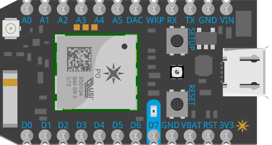
Pin Configuration and Descriptions
The Photon 1 has a total of 24 pins, including power, communication, and GPIO pins. Below is the pinout description:
| Pin | Name | Type | Description |
|---|---|---|---|
| 1 | VIN | Power Input | Input voltage (3.6V to 5.5V) |
| 2 | 3V3 | Power Output | Regulated 3.3V output |
| 3 | GND | Ground | Ground connection |
| 4 | D0 | Digital I/O | GPIO, PWM capable |
| 5 | D1 | Digital I/O | GPIO, PWM capable |
| 6 | D2 | Digital I/O | GPIO, PWM capable |
| 7 | D3 | Digital I/O | GPIO, PWM capable |
| 8 | D4 | Digital I/O | GPIO, PWM capable |
| 9 | D5 | Digital I/O | GPIO, PWM capable |
| 10 | D6 | Digital I/O | GPIO, PWM capable |
| 11 | D7 | Digital I/O | GPIO, PWM capable |
| 12 | A0 | Analog Input | 12-bit ADC input |
| 13 | A1 | Analog Input | 12-bit ADC input |
| 14 | A2 | Analog Input | 12-bit ADC input |
| 15 | A3 | Analog Input | 12-bit ADC input |
| 16 | A4 | Analog Input | 12-bit ADC input |
| 17 | A5 | Analog Input | 12-bit ADC input |
| 18 | RX | UART Input | UART receive pin |
| 19 | TX | UART Output | UART transmit pin |
| 20 | SCL | I2C Clock | I2C clock line |
| 21 | SDA | I2C Data | I2C data line |
| 22 | SPI_SCK | SPI Clock | SPI clock line |
| 23 | SPI_MOSI | SPI Data Out | SPI master out, slave in |
| 24 | SPI_MISO | SPI Data In | SPI master in, slave out |
Usage Instructions
The Photon 1 is designed to be easy to use in a variety of IoT projects. Below are the steps and best practices for using the component effectively.
How to Use the Photon 1 in a Circuit
Powering the Photon 1:
- Connect the VIN pin to a power source (3.6V to 5.5V).
- Alternatively, you can power the device via the micro-USB port if available.
- Ensure the GND pin is connected to the ground of your circuit.
Connecting to Wi-Fi:
- Use the built-in Wi-Fi module to connect to a wireless network.
- Configure the Wi-Fi credentials using the programming interface or a mobile app.
Programming the Photon 1:
- The Photon 1 can be programmed using the Particle IDE or Arduino IDE.
- Connect the Photon 1 to your computer via USB and upload your code.
Interfacing with Sensors and Actuators:
- Use the digital and analog pins to connect sensors and actuators.
- For communication, use the UART, SPI, or I2C pins as needed.
Important Considerations and Best Practices
- Voltage Levels: Ensure all connected devices operate at 3.3V logic levels to avoid damaging the Photon 1.
- Wi-Fi Signal Strength: Place the Photon 1 in an area with a strong Wi-Fi signal for reliable connectivity.
- Power Supply: Use a stable power source to prevent unexpected resets or malfunctions.
- Pin Usage: Avoid exceeding the current limits of the GPIO pins (max 20 mA per pin).
Example Code for Arduino IDE
Below is an example of how to blink an LED connected to pin D0 of the Photon 1:
// Define the pin for the LED
const int ledPin = D0;

void setup() {
  // Set the LED pin as an output
  pinMode(ledPin, OUTPUT);
}

void loop() {
  // Turn the LED on
  digitalWrite(ledPin, HIGH);
  delay(1000); // Wait for 1 second

  // Turn the LED off
  digitalWrite(ledPin, LOW);
  delay(1000); // Wait for 1 second
}
Troubleshooting and FAQs
Common Issues and Solutions
The Photon 1 is not connecting to Wi-Fi:
- Ensure the Wi-Fi credentials are correct.
- Check that the Wi-Fi network is operating at 2.4 GHz (not 5 GHz).
- Verify that the Photon 1 is within range of the Wi-Fi router.
The device is not powering on:
- Check the power supply voltage (must be between 3.6V and 5.5V).
- Ensure the GND pin is properly connected.
Code upload fails:
- Verify that the Photon 1 is in programming mode (check the onboard LED status).
- Ensure the correct COM port is selected in the IDE.
GPIO pins are not working as expected:
- Confirm that the pins are configured correctly in the code (e.g.,
pinMode). - Check for short circuits or incorrect wiring.
- Confirm that the pins are configured correctly in the code (e.g.,
FAQs
Can the Photon 1 operate on battery power?
Yes, the Photon 1 can be powered by a battery, provided the voltage is within the 3.6V to 5.5V range.What is the maximum range of the Wi-Fi module?
The Wi-Fi module typically has a range of up to 30 meters indoors and 100 meters outdoors, depending on environmental factors.Is the Photon 1 compatible with Arduino libraries?
Yes, the Photon 1 can be programmed using the Arduino IDE and supports many Arduino libraries.Can I use the Photon 1 for commercial products?
Yes, the Photon 1 is suitable for both prototyping and commercial applications.