Cirkit Designer Logo
Cirkit Designer
Your all-in-one circuit design IDE
Home / 
Component Documentation

How to Use SA868: Examples, Pinouts, and Specs

Image of SA868
Cirkit Designer LogoDesign with SA868 in Cirkit Designer

Introduction

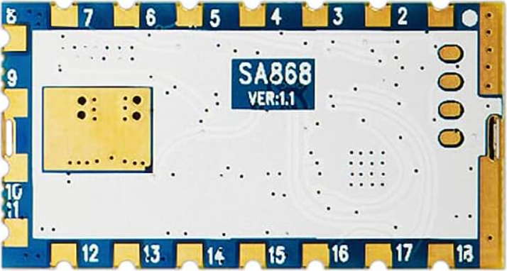
The SA868 is a low-power RF transmitter module designed for wireless communication applications. It operates in the 433 MHz frequency band, making it ideal for short-range communication tasks. This module is widely used in applications such as remote control systems, wireless sensor networks, and telemetry systems. Its compact design, low power consumption, and reliable performance make it a popular choice for developers and engineers.

Explore Projects Built with SA868

Use Cirkit Designer to design, explore, and prototype these projects online. Some projects support real-time simulation. Click "Open Project" to start designing instantly!
ESP8266 NodeMCU-Based Environmental Monitoring System with SIM900A GSM Communication
Image of IOE: A project utilizing SA868 in a practical application
This is a sensor-based data acquisition system with GSM communication capability. It uses an ESP8266 NodeMCU to collect environmental data from a DHT22 sensor and light levels from an LDR, as well as distance measurements from an HC-SR04 ultrasonic sensor. The SIM900A GSM module enables the system to transmit the collected data over a cellular network.
Cirkit Designer LogoOpen Project in Cirkit Designer
Arduino Mega 2560 Based Security System with Fingerprint Authentication and SMS Alerts
Image of Door security system: A project utilizing SA868 in a practical application
This circuit features an Arduino Mega 2560 microcontroller interfaced with a SIM800L GSM module, two fingerprint scanners, an I2C LCD display, an IR sensor, and a piezo buzzer. Power management is handled by a PowerBoost 1000 Basic Pad USB, a TP4056 charging module, and a Li-ion 18650 battery, with an option to use a Mini AC-DC 110V-230V to 5V 700mA module for direct power supply. The primary functionality appears to be a security system with GSM communication capabilities, biometric access control, and visual/audible feedback.
Cirkit Designer LogoOpen Project in Cirkit Designer
ESP32C3 and SIM800L Powered Smart Energy Monitor with OLED Display and Wi-Fi Connectivity
Image of SERVER: A project utilizing SA868 in a practical application
This circuit is a power monitoring system that uses an ESP32C3 microcontroller to collect power usage data from slave devices via WiFi and SMS. The collected data is displayed on a 0.96" OLED screen, and the system is powered by an AC-DC converter module. Additionally, the circuit includes a SIM800L GSM module for SMS communication and LEDs for status indication.
Cirkit Designer LogoOpen Project in Cirkit Designer
Solar-Powered Environmental Monitoring Station with GSM Reporting
Image of thesis nila po: A project utilizing SA868 in a practical application
This is a solar-powered monitoring and control system with automatic power source selection, environmental sensing, and communication capabilities. It uses an ESP32 microcontroller to process inputs from gas, flame, and temperature sensors, and to manage outputs like an LCD display, LEDs, and a buzzer. The system can communicate via a SIM900A module and switch between solar and AC power sources using an ATS.
Cirkit Designer LogoOpen Project in Cirkit Designer

Explore Projects Built with SA868

Use Cirkit Designer to design, explore, and prototype these projects online. Some projects support real-time simulation. Click "Open Project" to start designing instantly!
Image of IOE: A project utilizing SA868 in a practical application
ESP8266 NodeMCU-Based Environmental Monitoring System with SIM900A GSM Communication
This is a sensor-based data acquisition system with GSM communication capability. It uses an ESP8266 NodeMCU to collect environmental data from a DHT22 sensor and light levels from an LDR, as well as distance measurements from an HC-SR04 ultrasonic sensor. The SIM900A GSM module enables the system to transmit the collected data over a cellular network.
Cirkit Designer LogoOpen Project in Cirkit Designer
Image of Door security system: A project utilizing SA868 in a practical application
Arduino Mega 2560 Based Security System with Fingerprint Authentication and SMS Alerts
This circuit features an Arduino Mega 2560 microcontroller interfaced with a SIM800L GSM module, two fingerprint scanners, an I2C LCD display, an IR sensor, and a piezo buzzer. Power management is handled by a PowerBoost 1000 Basic Pad USB, a TP4056 charging module, and a Li-ion 18650 battery, with an option to use a Mini AC-DC 110V-230V to 5V 700mA module for direct power supply. The primary functionality appears to be a security system with GSM communication capabilities, biometric access control, and visual/audible feedback.
Cirkit Designer LogoOpen Project in Cirkit Designer
Image of SERVER: A project utilizing SA868 in a practical application
ESP32C3 and SIM800L Powered Smart Energy Monitor with OLED Display and Wi-Fi Connectivity
This circuit is a power monitoring system that uses an ESP32C3 microcontroller to collect power usage data from slave devices via WiFi and SMS. The collected data is displayed on a 0.96" OLED screen, and the system is powered by an AC-DC converter module. Additionally, the circuit includes a SIM800L GSM module for SMS communication and LEDs for status indication.
Cirkit Designer LogoOpen Project in Cirkit Designer
Image of thesis nila po: A project utilizing SA868 in a practical application
Solar-Powered Environmental Monitoring Station with GSM Reporting
This is a solar-powered monitoring and control system with automatic power source selection, environmental sensing, and communication capabilities. It uses an ESP32 microcontroller to process inputs from gas, flame, and temperature sensors, and to manage outputs like an LCD display, LEDs, and a buzzer. The system can communicate via a SIM900A module and switch between solar and AC power sources using an ATS.
Cirkit Designer LogoOpen Project in Cirkit Designer

Technical Specifications

The SA868 module is designed to provide efficient and reliable wireless communication. Below are its key technical specifications:

General Specifications

  • Frequency Band: 433 MHz
  • Operating Voltage: 3.3V to 5.0V
  • Transmit Power: Up to 20 dBm (100 mW)
  • Communication Range: Up to 1 km (line of sight)
  • Modulation Type: FSK (Frequency Shift Keying)
  • Current Consumption:
    • Transmit Mode: ~100 mA
    • Standby Mode: ~10 µA
  • Operating Temperature: -40°C to +85°C
  • Dimensions: 30 mm x 20 mm x 5 mm

Pin Configuration and Descriptions

The SA868 module has a simple pinout for easy integration into circuits. Below is the pin configuration:

Pin Number Pin Name Description
1 VCC Power supply input (3.3V to 5.0V).
2 GND Ground connection.
3 TXD UART Transmit pin for serial communication.
4 RXD UART Receive pin for serial communication.
5 PTT Push-to-Talk control pin (active low).
6 AUX Auxiliary pin for status indication.
7 ANT Antenna connection for RF signal transmission.

Usage Instructions

The SA868 module is straightforward to use in wireless communication projects. Below are the steps and best practices for integrating it into your circuit:

Basic Circuit Connection

  1. Power Supply: Connect the VCC pin to a 3.3V or 5.0V power source and the GND pin to the ground.
  2. UART Communication: Connect the TXD pin of the SA868 to the RX pin of your microcontroller (e.g., Arduino UNO) and the RXD pin of the SA868 to the TX pin of the microcontroller.
  3. PTT Control: Use the PTT pin to enable or disable transmission. Pull the pin low to activate transmission.
  4. Antenna: Attach a suitable 433 MHz antenna to the ANT pin for optimal signal transmission.

Example: Using SA868 with Arduino UNO

Below is an example of how to use the SA868 module with an Arduino UNO for basic communication:

Circuit Diagram

  • Connect the SA868's TXD to Arduino's RX (Pin 0).
  • Connect the SA868's RXD to Arduino's TX (Pin 1).
  • Connect the VCC and GND pins of the SA868 to the Arduino's 5V and GND, respectively.
  • Connect the PTT pin to a digital pin on the Arduino (e.g., Pin 7).

Arduino Code

// Example code to send data using the SA868 module with Arduino UNO

#define PTT_PIN 7  // Define the PTT pin connected to the SA868 module

void setup() {
  pinMode(PTT_PIN, OUTPUT);  // Set PTT pin as output
  digitalWrite(PTT_PIN, HIGH);  // Set PTT to HIGH (idle state)
  
  Serial.begin(9600);  // Initialize UART communication at 9600 baud rate
}

void loop() {
  digitalWrite(PTT_PIN, LOW);  // Activate transmission mode
  delay(10);  // Small delay to ensure the module is ready
  
  Serial.println("Hello, SA868!");  // Send data to the SA868 module
  
  delay(100);  // Wait for data to be transmitted
  digitalWrite(PTT_PIN, HIGH);  // Deactivate transmission mode
  
  delay(1000);  // Wait before sending the next message
}

Best Practices

  • Use a regulated power supply to avoid voltage fluctuations that may damage the module.
  • Ensure proper antenna placement to maximize communication range and minimize interference.
  • Avoid placing the module near high-frequency noise sources, such as switching power supplies.

Troubleshooting and FAQs

Common Issues and Solutions

  1. No Communication Between Devices

    • Cause: Incorrect UART connections or mismatched baud rates.
    • Solution: Verify that the TXD and RXD pins are correctly connected and that the baud rate matches the module's default (9600 bps).
  2. Short Communication Range

    • Cause: Poor antenna connection or placement.
    • Solution: Ensure the antenna is securely connected and positioned away from obstructions or interference sources.
  3. High Power Consumption

    • Cause: Module remains in transmit mode for extended periods.
    • Solution: Use the PTT pin to control transmission and minimize active time.
  4. Module Overheating

    • Cause: Prolonged high-power transmission.
    • Solution: Limit transmission duration and ensure adequate ventilation.

FAQs

  • Q: Can the SA868 operate at frequencies other than 433 MHz?
    A: No, the SA868 is specifically designed for the 433 MHz frequency band.

  • Q: What is the maximum communication range of the SA868?
    A: The module can achieve up to 1 km range in line-of-sight conditions with a proper antenna.

  • Q: Can I use the SA868 with a 3.3V microcontroller?
    A: Yes, the SA868 supports an operating voltage range of 3.3V to 5.0V, making it compatible with 3.3V systems.

  • Q: How do I change the module's settings (e.g., baud rate)?
    A: The SA868 supports AT commands for configuration. Refer to the module's datasheet for detailed instructions.

By following this documentation, you can effectively integrate and use the SA868 module in your wireless communication projects.