Cirkit Designer
Your all-in-one circuit design IDE
Home /
Component Documentation
How to Use Wireless Relay 12v 4Ch: Examples, Pinouts, and Specs
Introduction
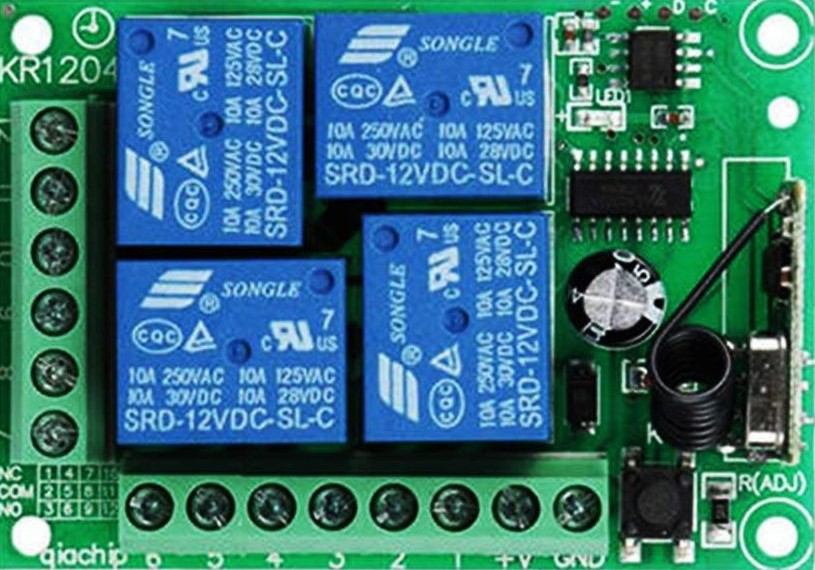
The WenQia Wireless Relay 12V 4Ch is a versatile and robust relay module designed for remote control of multiple devices or circuits. Operating at 12 volts, this module features four independent channels, making it ideal for applications that require the control of multiple devices simultaneously. Common use cases include home automation, industrial control systems, and remote switching applications.
Explore Projects Built with Wireless Relay 12v 4Ch
Wi-Fi Controlled 4-Channel Relay System with Arduino and ESP8266
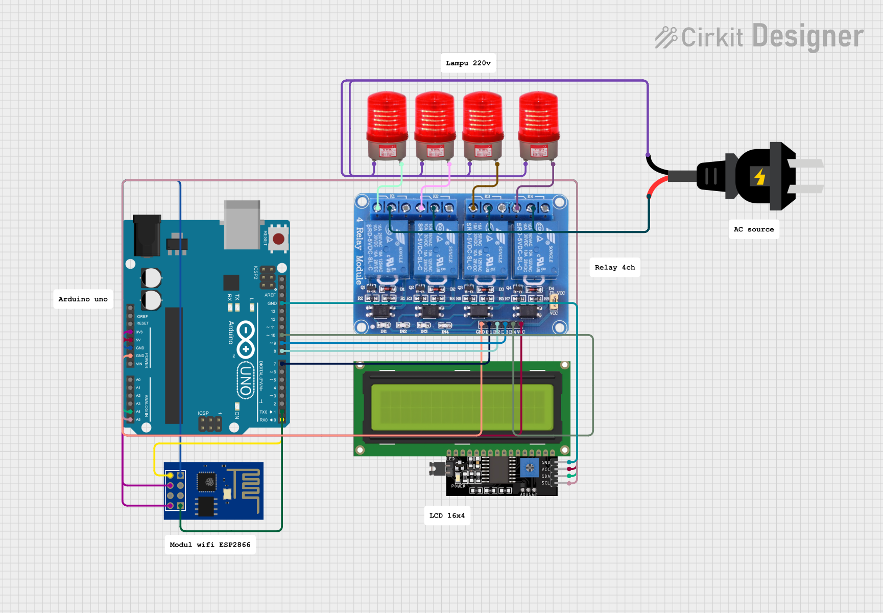
This circuit is a Wi-Fi controlled 4-channel relay system using an Arduino UNO and an ESP8266 module. The relays can be controlled via a web interface served by the ESP8266, and the status of each relay is displayed on a 16x4 I2C LCD. The relays are used to control four 220V AC red lights, and the Arduino communicates with the ESP8266 via serial communication.
Wi-Fi Controlled Relay System Using ESP8266

This circuit uses an ESP8266 microcontroller to control a 4-channel relay module, which can switch various loads. The ESP8266 is powered by a 12V DC supply converted from an AC source, and it interfaces with the relay module to control the relays via its digital output pins.
ESP8266 and HC-05 Bluetooth-Based Home Automation System with 4-Channel Relay Control
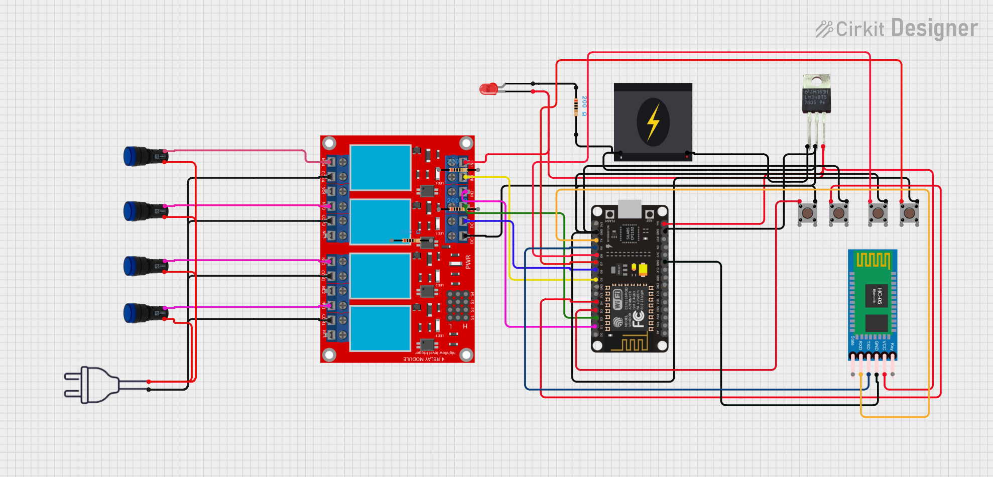
This circuit is a Bluetooth-based home automation system that uses an ESP8266 NodeMCU to control a 4-channel relay module. The relays can be toggled via Bluetooth commands received from an HC-05 Bluetooth module or by pressing connected pushbuttons. The system also includes pilot lamps to indicate the status of each relay.
Wi-Fi Controlled Smart Relay Switch with ESP8266 and MCP23017

This circuit is designed to control an 8-channel relay module via an ESP8266 microcontroller, which interfaces with an MCP23017 I/O expander over I2C. The ESP8266 connects to a WiFi network and subscribes to MQTT topics to receive commands for toggling the relays. Additionally, there are toggle switches connected to the MCP23017 that allow manual control of the relays, with the system's state being reported back via MQTT.
Explore Projects Built with Wireless Relay 12v 4Ch
Wi-Fi Controlled 4-Channel Relay System with Arduino and ESP8266
This circuit is a Wi-Fi controlled 4-channel relay system using an Arduino UNO and an ESP8266 module. The relays can be controlled via a web interface served by the ESP8266, and the status of each relay is displayed on a 16x4 I2C LCD. The relays are used to control four 220V AC red lights, and the Arduino communicates with the ESP8266 via serial communication.
Wi-Fi Controlled Relay System Using ESP8266
This circuit uses an ESP8266 microcontroller to control a 4-channel relay module, which can switch various loads. The ESP8266 is powered by a 12V DC supply converted from an AC source, and it interfaces with the relay module to control the relays via its digital output pins.
ESP8266 and HC-05 Bluetooth-Based Home Automation System with 4-Channel Relay Control
This circuit is a Bluetooth-based home automation system that uses an ESP8266 NodeMCU to control a 4-channel relay module. The relays can be toggled via Bluetooth commands received from an HC-05 Bluetooth module or by pressing connected pushbuttons. The system also includes pilot lamps to indicate the status of each relay.
Wi-Fi Controlled Smart Relay Switch with ESP8266 and MCP23017
This circuit is designed to control an 8-channel relay module via an ESP8266 microcontroller, which interfaces with an MCP23017 I/O expander over I2C. The ESP8266 connects to a WiFi network and subscribes to MQTT topics to receive commands for toggling the relays. Additionally, there are toggle switches connected to the MCP23017 that allow manual control of the relays, with the system's state being reported back via MQTT.
Technical Specifications
Key Technical Details
| Parameter | Value |
|---|---|
| Operating Voltage | 12V DC |
| Channels | 4 |
| Relay Type | SPDT (Single Pole Double Throw) |
| Max Load Current | 10A per channel |
| Max Load Voltage | 250V AC / 30V DC |
| Wireless Frequency | 433MHz |
| Control Distance | Up to 100 meters (open space) |
| Dimensions | 135mm x 75mm x 18mm |
Pin Configuration and Descriptions
| Pin Number | Pin Name | Description |
|---|---|---|
| 1 | VCC | Power supply input (12V DC) |
| 2 | GND | Ground |
| 3 | IN1 | Control signal input for Relay 1 |
| 4 | IN2 | Control signal input for Relay 2 |
| 5 | IN3 | Control signal input for Relay 3 |
| 6 | IN4 | Control signal input for Relay 4 |
| 7 | NO1 | Normally Open contact for Relay 1 |
| 8 | COM1 | Common contact for Relay 1 |
| 9 | NC1 | Normally Closed contact for Relay 1 |
| 10 | NO2 | Normally Open contact for Relay 2 |
| 11 | COM2 | Common contact for Relay 2 |
| 12 | NC2 | Normally Closed contact for Relay 2 |
| 13 | NO3 | Normally Open contact for Relay 3 |
| 14 | COM3 | Common contact for Relay 3 |
| 15 | NC3 | Normally Closed contact for Relay 3 |
| 16 | NO4 | Normally Open contact for Relay 4 |
| 17 | COM4 | Common contact for Relay 4 |
| 18 | NC4 | Normally Closed contact for Relay 4 |
Usage Instructions
How to Use the Component in a Circuit
Power Supply Connection:
- Connect the VCC pin to a 12V DC power supply.
- Connect the GND pin to the ground of the power supply.
Control Signal Inputs:
- Connect the IN1, IN2, IN3, and IN4 pins to the control signals from a microcontroller or other control device.
Relay Outputs:
- Connect the devices or circuits to be controlled to the NO (Normally Open), COM (Common), and NC (Normally Closed) contacts of each relay.
Important Considerations and Best Practices
- Ensure that the power supply voltage is stable and within the specified range (12V DC).
- Avoid exceeding the maximum load current and voltage ratings for each relay channel.
- Use proper isolation techniques when controlling high voltage or high current loads.
- Keep the wireless receiver and antenna away from sources of interference to maintain reliable communication.
Example Code for Arduino UNO
/*
 * Example code to control the WenQia Wireless Relay 12V 4Ch using Arduino UNO.
 * This code demonstrates how to turn on and off each relay channel.
 */

const int relay1 = 2; // Control pin for Relay 1
const int relay2 = 3; // Control pin for Relay 2
const int relay3 = 4; // Control pin for Relay 3
const int relay4 = 5; // Control pin for Relay 4

void setup() {
  // Initialize the relay control pins as outputs
  pinMode(relay1, OUTPUT);
  pinMode(relay2, OUTPUT);
  pinMode(relay3, OUTPUT);
  pinMode(relay4, OUTPUT);
}

void loop() {
  // Turn on Relay 1
  digitalWrite(relay1, HIGH);
  delay(1000); // Wait for 1 second

  // Turn off Relay 1
  digitalWrite(relay1, LOW);
  delay(1000); // Wait for 1 second

  // Turn on Relay 2
  digitalWrite(relay2, HIGH);
  delay(1000); // Wait for 1 second

  // Turn off Relay 2
  digitalWrite(relay2, LOW);
  delay(1000); // Wait for 1 second

  // Turn on Relay 3
  digitalWrite(relay3, HIGH);
  delay(1000); // Wait for 1 second

  // Turn off Relay 3
  digitalWrite(relay3, LOW);
  delay(1000); // Wait for 1 second

  // Turn on Relay 4
  digitalWrite(relay4, HIGH);
  delay(1000); // Wait for 1 second

  // Turn off Relay 4
  digitalWrite(relay4, LOW);
  delay(1000); // Wait for 1 second
}
Troubleshooting and FAQs
Common Issues Users Might Face
Relay Not Activating:
- Ensure that the control signal voltage is within the required range.
- Check the power supply voltage and connections.
Intermittent Operation:
- Verify that the wireless receiver is not experiencing interference.
- Ensure that the control signals are stable and not fluctuating.
Overheating:
- Ensure that the load current does not exceed the maximum rating.
- Provide adequate ventilation and cooling for high-power applications.
Solutions and Tips for Troubleshooting
- Check Connections: Ensure all connections are secure and correctly wired.
- Verify Power Supply: Use a stable and adequate power supply to avoid voltage drops.
- Use Proper Isolation: For high voltage or high current loads, use proper isolation techniques to protect the relay module and control device.
- Test with Simple Loads: Start by testing the relay module with simple loads (e.g., LEDs) before connecting more complex devices.
By following these guidelines and best practices, users can effectively utilize the WenQia Wireless Relay 12V 4Ch in their projects and applications.