
How to Use DC-DC Buck Converter 6-14V -> 5V 8A: Examples, Pinouts, and Specs
 Design with DC-DC Buck Converter 6-14V -> 5V 8A in Cirkit Designer
Introduction
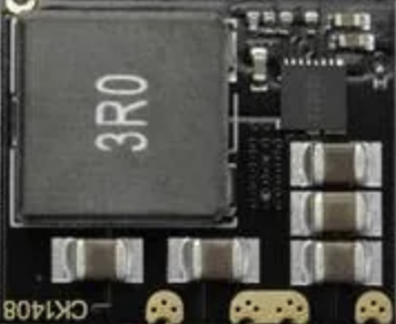
The DFR 0753 is a high-performance DC-DC buck converter manufactured by DFRobot. It is designed to step down an input voltage ranging from 6V to 14V to a stable 5V output, with a maximum current capacity of 8A. This makes it ideal for powering a wide range of electronic devices, including microcontrollers, sensors, and other peripherals that require a reliable 5V power source.
Explore Projects Built with DC-DC Buck Converter 6-14V -> 5V 8A
 Open Project in Cirkit Designer
 Open Project in Cirkit Designer
 Open Project in Cirkit Designer
 Open Project in Cirkit Designer
Explore Projects Built with DC-DC Buck Converter 6-14V -> 5V 8A
Open Project in Cirkit DesignerOpen Project in Cirkit DesignerOpen Project in Cirkit DesignerOpen Project in Cirkit DesignerCommon Applications and Use Cases
- Powering microcontrollers such as Arduino, Raspberry Pi, or ESP32.
- Supplying power to USB-powered devices.
- Driving high-current loads like motors, LEDs, or relays.
- Battery-powered systems requiring efficient voltage regulation.
- Robotics and IoT applications.
Technical Specifications
Below are the key technical details of the DFR 0753 DC-DC buck converter:
| Parameter | Value |
|---|---|
| Input Voltage Range | 6V to 14V |
| Output Voltage | 5V (regulated) |
| Maximum Output Current | 8A |
| Efficiency | Up to 95% |
| Switching Frequency | 300 kHz |
| Operating Temperature | -40°C to +85°C |
| Dimensions | 50mm x 25mm x 15mm |
| Weight | 20g |
Pin Configuration and Descriptions
The DFR 0753 has the following pin configuration:
| Pin Name | Description |
|---|---|
| VIN | Input voltage pin (connect to 6-14V power source). |
| GND | Ground pin (common ground for input and output). |
| VOUT | Regulated 5V output pin (connect to the load). |
Usage Instructions
How to Use the Component in a Circuit
Connect the Input Voltage:
- Connect the VIN pin to a DC power source with a voltage between 6V and 14V.
- Ensure the power source can supply sufficient current for your load (including some margin for efficiency losses).
Connect the Ground:
- Connect the GND pin to the ground of your circuit. This serves as the common ground for both input and output.
Connect the Output Load:
- Connect the VOUT pin to the device or circuit requiring a 5V power supply.
- Ensure the total current drawn by the load does not exceed 8A.
Power On:
- Once all connections are secure, power on the input source. The converter will regulate the input voltage to provide a stable 5V output.
Important Considerations and Best Practices
- Heat Dissipation: At high currents, the converter may generate heat. Use a heatsink or ensure proper ventilation to prevent overheating.
- Input Voltage Range: Do not exceed the specified input voltage range (6-14V) to avoid damaging the converter.
- Load Current: Ensure the total load current does not exceed 8A to maintain stable operation and prevent damage.
- Capacitor Placement: For optimal performance, place decoupling capacitors close to the input and output pins to reduce noise and improve stability.
- Polarity Protection: Double-check the polarity of the input and output connections to avoid reverse polarity damage.
Example: Using with Arduino UNO
The DFR 0753 can be used to power an Arduino UNO by providing a stable 5V supply. Below is an example circuit and code:
Circuit Connections
- Connect the VIN pin of the buck converter to a 12V DC power source.
- Connect the GND pin of the buck converter to the ground of the power source and the Arduino.
- Connect the VOUT pin of the buck converter to the 5V pin of the Arduino UNO.
Example Code
// Example code for Arduino UNO powered by DFR 0753 DC-DC Buck Converter
// This code blinks an LED connected to pin 13 of the Arduino UNO.

void setup() {
  pinMode(13, OUTPUT); // Set pin 13 as an output pin
}

void loop() {
  digitalWrite(13, HIGH); // Turn the LED on
  delay(1000);            // Wait for 1 second
  digitalWrite(13, LOW);  // Turn the LED off
  delay(1000);            // Wait for 1 second
}
Troubleshooting and FAQs
Common Issues and Solutions
| Issue | Possible Cause | Solution |
|---|---|---|
| No output voltage | Incorrect wiring or loose connections | Double-check all connections, especially VIN, GND, and VOUT. |
| Output voltage is unstable | Insufficient input voltage or noisy power source | Ensure the input voltage is within the 6-14V range and use decoupling capacitors. |
| Overheating during operation | High current draw or poor ventilation | Reduce the load current or add a heatsink for better heat dissipation. |
| Load not receiving power | Load exceeds 8A current limit | Ensure the total load current is within the 8A limit. |
Frequently Asked Questions
Can I use this converter with a 24V power source?
- No, the input voltage range is limited to 6V to 14V. Using a 24V source will damage the converter.
What happens if I exceed the 8A current limit?
- Exceeding the current limit may cause the converter to overheat, shut down, or become permanently damaged.
Is the output voltage adjustable?
- No, the output voltage is fixed at 5V.
Can I use this converter to power a Raspberry Pi?
- Yes, the converter can provide a stable 5V supply for a Raspberry Pi, as long as the total current draw (including peripherals) does not exceed 8A.
By following this documentation, you can effectively integrate the DFR 0753 DC-DC buck converter into your projects for reliable and efficient power regulation.