
How to Use mon CC1101: Examples, Pinouts, and Specs
 Design with mon CC1101 in Cirkit Designer
Introduction
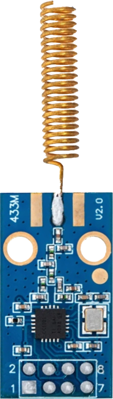
The CC1101, manufactured by Ali, is a low-power sub-1 GHz transceiver designed for wireless communication in the ISM (Industrial, Scientific, and Medical) frequency bands. It supports multiple modulation formats, including ASK, FSK, GFSK, and MSK, making it versatile for a wide range of applications. The CC1101 is widely used in remote control systems, wireless sensor networks, home automation, and industrial monitoring due to its low power consumption and robust performance.
Explore Projects Built with mon CC1101
 Open Project in Cirkit Designer
 Open Project in Cirkit Designer
 Open Project in Cirkit Designer
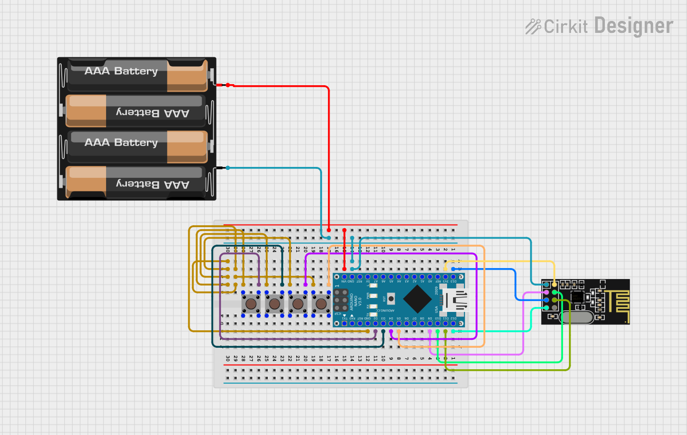 Open Project in Cirkit Designer
Explore Projects Built with mon CC1101
Open Project in Cirkit DesignerOpen Project in Cirkit DesignerOpen Project in Cirkit DesignerOpen Project in Cirkit DesignerCommon Applications:
- Remote control systems (e.g., garage doors, drones)
- Wireless sensor networks
- Home automation (e.g., smart lighting, thermostats)
- Industrial monitoring and control
- Alarm and security systems
Technical Specifications
The CC1101 is a highly configurable transceiver with the following key specifications:
| Parameter | Value |
|---|---|
| Frequency Range | 300 MHz to 928 MHz |
| Modulation Formats | ASK, FSK, GFSK, MSK |
| Data Rate | 0.6 kbps to 600 kbps |
| Supply Voltage | 1.8 V to 3.6 V |
| Current Consumption | 14.7 mA (RX mode), 34.2 mA (TX mode @ 10 dBm) |
| Output Power | Up to +12 dBm |
| Sensitivity | -116 dBm at 1.2 kbps |
| Operating Temperature | -40°C to +85°C |
| Interface | SPI (Serial Peripheral Interface) |
Pin Configuration and Descriptions
The CC1101 is typically available in a 20-pin QFN package. Below is the pin configuration:
| Pin Number | Pin Name | Description |
|---|---|---|
| 1 | GND | Ground connection |
| 2 | GDO2 | General-purpose digital output 2 |
| 3 | GDO0 | General-purpose digital output 0 |
| 4 | GDO1 | General-purpose digital output 1 |
| 5 | VDD | Power supply (1.8 V to 3.6 V) |
| 6 | SI | SPI data input |
| 7 | SO | SPI data output |
| 8 | SCLK | SPI clock |
| 9 | CSn | SPI chip select (active low) |
| 10 | GND | Ground connection |
| 11-20 | RF_P/RF_N | Differential RF input/output |
Usage Instructions
How to Use the CC1101 in a Circuit
- Power Supply: Connect the VDD pin to a stable power source (1.8 V to 3.6 V) and ensure proper decoupling capacitors are placed near the VDD pin for noise reduction.
- SPI Communication: Use the SPI interface (pins SI, SO, SCLK, and CSn) to configure the CC1101 and send/receive data. Ensure the microcontroller supports SPI communication.
- Antenna Connection: Connect an appropriate antenna to the RF_P and RF_N pins for optimal wireless performance. Use a matching network if necessary.
- GPIO Configuration: Configure the GDO pins for specific functions such as interrupts, data ready signals, or other custom uses.
- Crystal Oscillator: Connect a 26 MHz crystal oscillator to the CC1101 for proper operation.
Important Considerations and Best Practices
- Frequency Selection: Ensure the operating frequency complies with local regulations (e.g., 433 MHz, 868 MHz, or 915 MHz).
- Antenna Design: Use a well-designed antenna and matching network to maximize range and minimize interference.
- Power Management: Utilize the low-power modes of the CC1101 to extend battery life in portable applications.
- SPI Timing: Follow the SPI timing requirements specified in the datasheet to avoid communication errors.
Example Code for Arduino UNO
Below is an example of how to interface the CC1101 with an Arduino UNO using the SPI library:
#include <SPI.h>

// Define CC1101 pins
#define CC1101_CS 10  // Chip select pin
#define CC1101_GDO0 2 // GDO0 pin for interrupt

void setup() {
  // Initialize serial communication for debugging
  Serial.begin(9600);

  // Initialize SPI
  SPI.begin();
  pinMode(CC1101_CS, OUTPUT);
  digitalWrite(CC1101_CS, HIGH); // Set CS high initially

  // Configure GDO0 as input
  pinMode(CC1101_GDO0, INPUT);

  // Reset CC1101
  resetCC1101();

  // Example: Set CC1101 to idle mode
  writeCC1101Command(0x36); // Send SIDLE command
  Serial.println("CC1101 initialized and set to idle mode.");
}

void loop() {
  // Example: Check if data is received
  if (digitalRead(CC1101_GDO0) == HIGH) {
    Serial.println("Data received!");
    // Add code to read data from CC1101
  }
}

// Function to reset CC1101
void resetCC1101() {
  digitalWrite(CC1101_CS, LOW);
  delay(1);
  digitalWrite(CC1101_CS, HIGH);
  delay(1);
  digitalWrite(CC1101_CS, LOW);
  delay(1);
  digitalWrite(CC1101_CS, HIGH);
  delay(1);
}

// Function to send a command to CC1101
void writeCC1101Command(byte command) {
  digitalWrite(CC1101_CS, LOW);
  SPI.transfer(command);
  digitalWrite(CC1101_CS, HIGH);
}
Troubleshooting and FAQs
Common Issues
No Communication with CC1101:
- Cause: Incorrect SPI wiring or configuration.
- Solution: Double-check the SPI connections and ensure the microcontroller's SPI settings match the CC1101's requirements.
Poor Wireless Range:
- Cause: Improper antenna design or placement.
- Solution: Use a properly tuned antenna and ensure it is placed away from sources of interference.
High Power Consumption:
- Cause: CC1101 not entering low-power mode.
- Solution: Verify that the CC1101 is configured to enter sleep or idle mode when not transmitting or receiving.
Data Loss or Corruption:
- Cause: Incorrect data rate or modulation settings.
- Solution: Ensure the transmitter and receiver are configured with the same data rate, frequency, and modulation format.
FAQs
Can the CC1101 operate at 2.4 GHz?
- No, the CC1101 is designed for sub-1 GHz frequencies (300 MHz to 928 MHz).
What is the maximum range of the CC1101?
- The range depends on the antenna, output power, and environmental conditions. Typically, it can achieve up to 500 meters in open space with a good antenna.
Is the CC1101 compatible with Arduino?
- Yes, the CC1101 can be interfaced with Arduino using the SPI library and appropriate libraries for CC1101 configuration.
Does the CC1101 support encryption?
- No, the CC1101 does not have built-in encryption. However, encryption can be implemented in software on the microcontroller.