How to Use OBD II (mirrored): Examples, Pinouts, and Specs
Introduction
The OBD II (On-Board Diagnostics II) is a standardized system implemented in most vehicles manufactured after 1996. It is designed to monitor and report on the performance of the engine, emissions system, and other critical vehicle systems. The "mirrored" aspect refers to a specific configuration or display of OBD II data, which may involve duplicating or formatting the diagnostic information for easier reading or interpretation, such as on a secondary display or diagnostic tool.
Common applications of the OBD II system include:
- Vehicle diagnostics and troubleshooting.
- Emissions testing and compliance.
- Real-time performance monitoring.
- Integration with third-party tools for advanced analytics or custom displays.
Explore Projects Built with OBD II (mirrored)
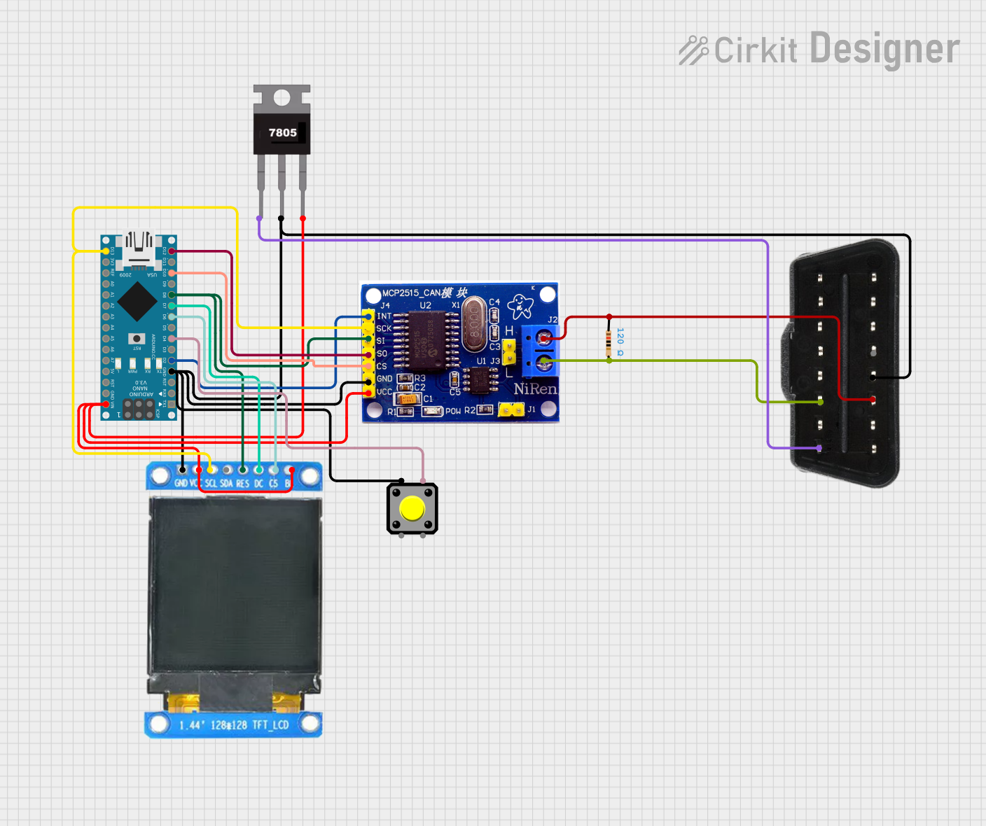
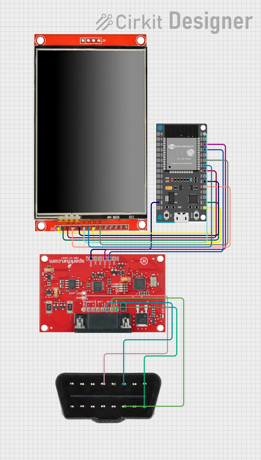
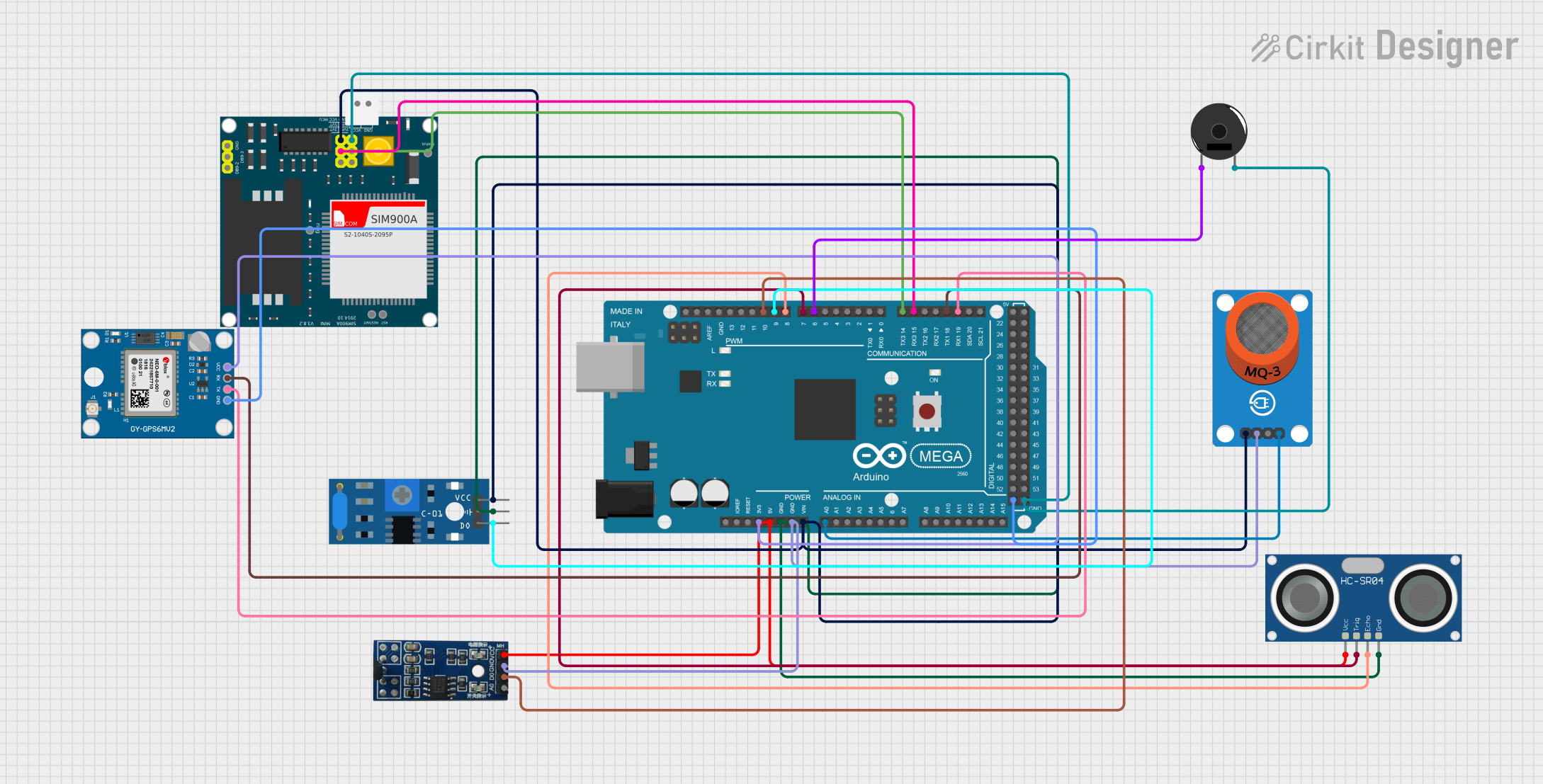
Explore Projects Built with OBD II (mirrored)
Technical Specifications
Key Technical Details
- Protocol Standards: Supports multiple OBD II protocols, including:
- SAE J1850 PWM (Pulse Width Modulation)
- SAE J1850 VPW (Variable Pulse Width)
- ISO 9141-2
- ISO 14230-4 (KWP2000)
- ISO 15765-4 (CAN bus)
- Operating Voltage: 12V DC (vehicle battery power).
- Communication Interface: Typically uses a 16-pin DLC (Data Link Connector).
- Data Rate: Varies by protocol, typically up to 500 kbps for CAN bus.
- Output Format: Diagnostic Trouble Codes (DTCs) and real-time data in hexadecimal or human-readable format.
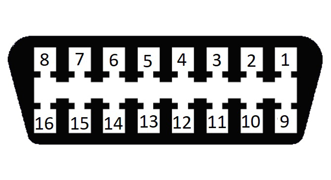
Pin Configuration and Descriptions
The OBD II connector is a 16-pin standardized interface. Below is the pinout configuration:
| Pin Number | Name | Description |
|---|---|---|
| 1 | Vendor Option | Manufacturer-specific use. |
| 2 | J1850 Bus+ | Positive line of the SAE J1850 protocol. |
| 3 | Vendor Option | Manufacturer-specific use. |
| 4 | Chassis Ground | Ground connection to the vehicle chassis. |
| 5 | Signal Ground | Ground for signal reference. |
| 6 | CAN High (J-2284) | High line of the CAN bus. |
| 7 | ISO 9141-2 K-Line | Communication line for ISO 9141-2 and ISO 14230-4 protocols. |
| 8 | Vendor Option | Manufacturer-specific use. |
| 9 | Vendor Option | Manufacturer-specific use. |
| 10 | J1850 Bus- | Negative line of the SAE J1850 protocol. |
| 11 | Vendor Option | Manufacturer-specific use. |
| 12 | Vendor Option | Manufacturer-specific use. |
| 13 | Vendor Option | Manufacturer-specific use. |
| 14 | CAN Low (J-2284) | Low line of the CAN bus. |
| 15 | ISO 9141-2 L-Line | Optional line for ISO 9141-2 and ISO 14230-4 protocols. |
| 16 | Battery Power | Direct connection to the vehicle's battery (12V). |
Usage Instructions
How to Use the OBD II (Mirrored) in a Circuit
- Locate the OBD II Port: The OBD II port is typically located under the dashboard near the driver's seat.
- Connect the OBD II Device: Plug the OBD II diagnostic tool or adapter into the 16-pin connector.
- Power On the Vehicle: Turn the ignition key to the "ON" position (engine off or running, depending on the diagnostic tool's requirements).
- Access Data: Use a compatible diagnostic tool or software to read and interpret the data. For mirrored configurations, ensure the tool supports the specific display or duplication feature.
Important Considerations and Best Practices
- Ensure the diagnostic tool is compatible with the vehicle's OBD II protocol.
- Avoid leaving the OBD II device connected for extended periods to prevent battery drain.
- Use a reliable and well-insulated adapter to avoid electrical shorts or damage.
- For mirrored configurations, verify that the secondary display or tool is properly synchronized with the primary OBD II data.
Example: Using OBD II with Arduino UNO
You can use an Arduino UNO with an OBD II adapter (e.g., ELM327) to read vehicle data. Below is an example code snippet:
#include <SoftwareSerial.h>

// Define RX and TX pins for SoftwareSerial
SoftwareSerial mySerial(10, 11); // RX = pin 10, TX = pin 11

void setup() {
  Serial.begin(9600); // Initialize hardware serial for debugging
  mySerial.begin(9600); // Initialize software serial for OBD II communication

  Serial.println("Initializing OBD II connection...");
  mySerial.println("ATZ"); // Reset the OBD II adapter
  delay(1000);

  mySerial.println("ATE0"); // Disable echo for cleaner output
  delay(1000);

  mySerial.println("010C"); // Request engine RPM (PID 0C)
}

void loop() {
  if (mySerial.available()) {
    // Read data from OBD II adapter
    String data = mySerial.readStringUntil('\r');
    Serial.println("OBD II Data: " + data); // Print data to Serial Monitor
  }
}
Note: Ensure the OBD II adapter is connected to the Arduino UNO's RX and TX pins as specified. The adapter should also be plugged into the vehicle's OBD II port.
Troubleshooting and FAQs
Common Issues
No Data Received:
- Ensure the OBD II adapter is securely connected to the vehicle's port.
- Verify that the ignition is in the "ON" position.
- Check the compatibility of the diagnostic tool with the vehicle's protocol.
Incorrect or Garbled Data:
- Confirm the baud rate settings match between the OBD II adapter and the microcontroller.
- Disable echo commands (e.g.,
ATE0) to avoid redundant characters.
Device Not Powering On:
- Check the vehicle's battery voltage (should be 12V).
- Inspect the OBD II adapter for physical damage or loose connections.
FAQs
Q: Can I use OBD II on older vehicles?
A: OBD II is only supported on vehicles manufactured after 1996. For older vehicles, you may need an OBD I adapter.Q: What is the "mirrored" feature?
A: The mirrored feature refers to duplicating or formatting OBD II data for easier interpretation, such as displaying it on a secondary screen or diagnostic tool.Q: Is it safe to leave the OBD II adapter connected while driving?
A: Yes, but prolonged use may drain the vehicle's battery if the adapter remains connected when the engine is off.Q: Can I clear diagnostic trouble codes (DTCs) using OBD II?
A: Yes, most OBD II tools allow you to clear DTCs, but ensure the underlying issue is resolved before doing so.