How to Use lora e22: Examples, Pinouts, and Specs
Introduction
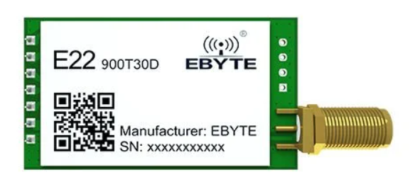
The LoRa E22, manufactured by Ebyte, is a long-range, low-power wireless transceiver module designed for communication in the 433MHz, 868MHz, and 915MHz frequency bands. It leverages LoRa (Long Range) modulation technology to enable reliable, long-distance communication with minimal power consumption. This makes it an excellent choice for Internet of Things (IoT) applications, remote monitoring, smart agriculture, and industrial automation.
Explore Projects Built with lora e22
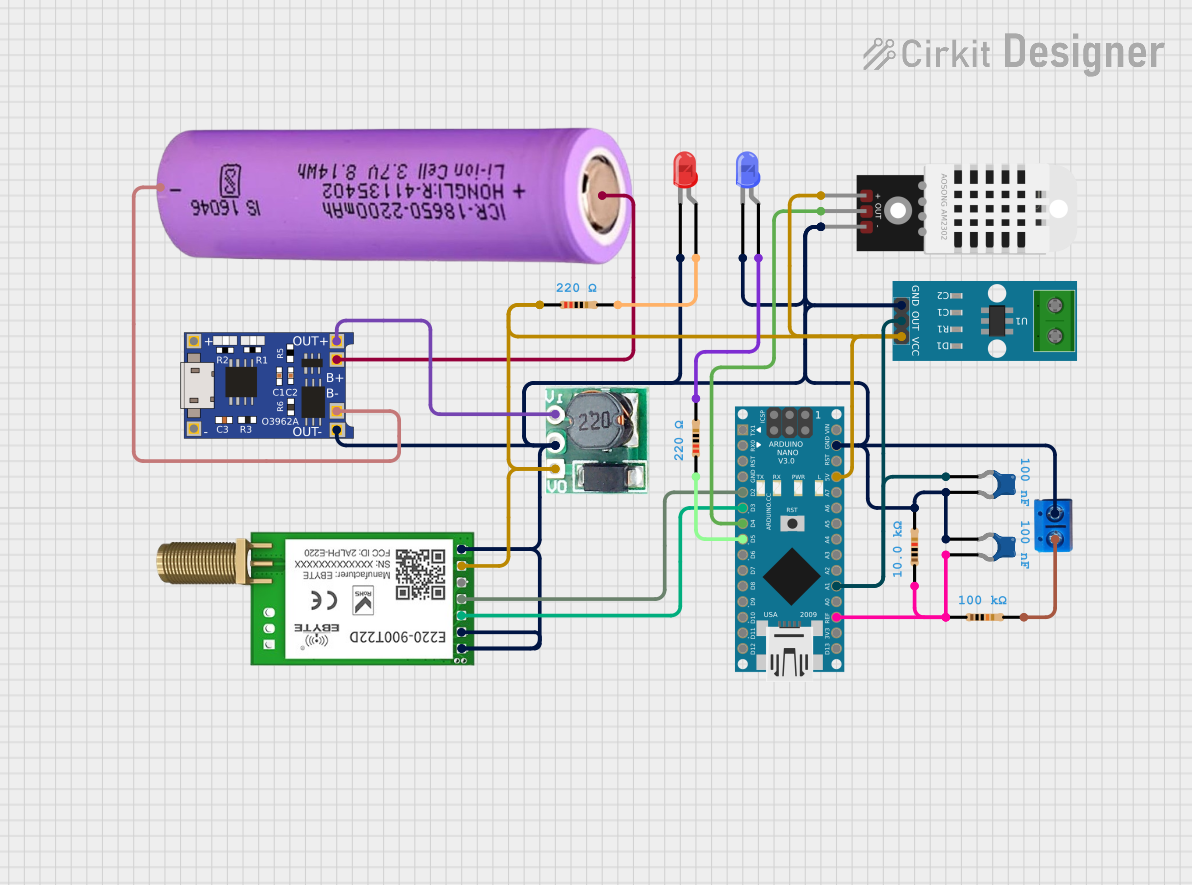
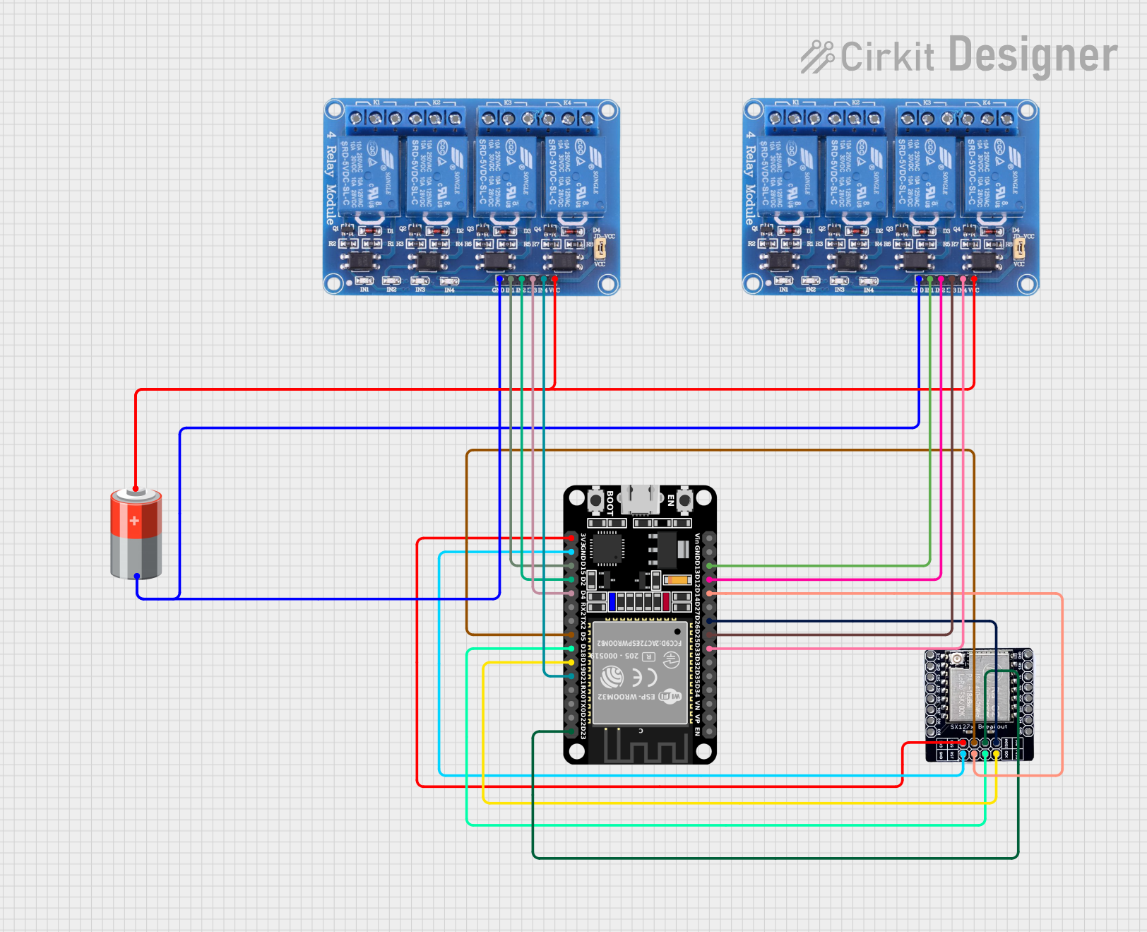
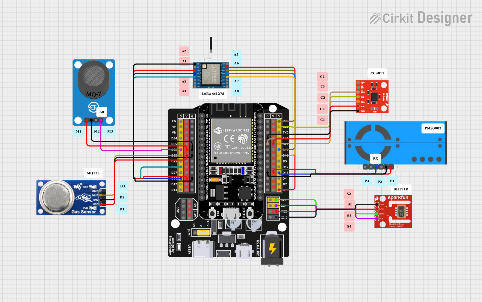

Explore Projects Built with lora e22
Common Applications and Use Cases
- IoT networks for smart cities and homes
- Remote environmental monitoring systems
- Smart agriculture and irrigation systems
- Industrial automation and telemetry
- Wireless sensor networks
- Long-range communication in rural or remote areas
Technical Specifications
The LoRa E22 module is packed with features that make it versatile and efficient for a wide range of applications. Below are its key technical specifications:
General Specifications
| Parameter | Value |
|---|---|
| Frequency Bands | 433MHz / 868MHz / 915MHz |
| Modulation Technology | LoRa (Long Range) |
| Communication Distance | Up to 5 km (line of sight, open area) |
| Power Output | Up to 30 dBm (1W) |
| Sensitivity | -139 dBm |
| Data Rate | 0.3 kbps to 19.2 kbps |
| Operating Voltage | 3.3V to 5.5V |
| Operating Current | 120 mA (transmit), 16 mA (receive) |
| Sleep Current | < 2 µA |
| Operating Temperature | -40°C to +85°C |
| Dimensions | 22 mm x 16 mm x 3 mm |
Pin Configuration and Descriptions
The LoRa E22 module has a total of 8 pins. Below is the pinout and description:
| Pin Number | Pin Name | Description |
|---|---|---|
| 1 | M0 | Mode selection pin 0 |
| 2 | M1 | Mode selection pin 1 |
| 3 | RXD | UART data input (connect to MCU TX) |
| 4 | TXD | UART data output (connect to MCU RX) |
| 5 | AUX | Module status indicator |
| 6 | VCC | Power supply (3.3V to 5.5V) |
| 7 | GND | Ground |
| 8 | ANT | Antenna interface |
Usage Instructions
The LoRa E22 module is easy to integrate into your projects. Below are the steps and best practices for using the module:
Connecting the Module
- Power Supply: Connect the
VCCpin to a 3.3V or 5V power source and theGNDpin to ground. - UART Communication: Connect the
RXDpin to the TX pin of your microcontroller and theTXDpin to the RX pin of your microcontroller. - Mode Selection: Use the
M0andM1pins to configure the module's operating mode:- Mode 0 (Normal): M0 = 0, M1 = 0
- Mode 1 (Wake-up): M0 = 1, M1 = 0
- Mode 2 (Power-saving): M0 = 0, M1 = 1
- Mode 3 (Configuration): M0 = 1, M1 = 1
- Antenna: Attach a compatible antenna to the
ANTpin for optimal performance.
Example: Using LoRa E22 with Arduino UNO
Below is an example of how to use the LoRa E22 module with an Arduino UNO for basic communication:
Wiring Diagram
| LoRa E22 Pin | Arduino UNO Pin |
|---|---|
| VCC | 5V |
| GND | GND |
| RXD | D3 |
| TXD | D2 |
| M0 | GND |
| M1 | GND |
| AUX | Not connected |
| ANT | Antenna |
Arduino Code
#include <SoftwareSerial.h>

// Define software serial pins for communication with LoRa E22
SoftwareSerial LoRaSerial(2, 3); // RX = D2, TX = D3

void setup() {
  // Initialize serial communication
  Serial.begin(9600); // For debugging via Serial Monitor
  LoRaSerial.begin(9600); // Communication with LoRa E22

  Serial.println("LoRa E22 Module Test");
}

void loop() {
  // Send data to LoRa E22
  LoRaSerial.println("Hello, LoRa!");

  // Check if data is received from LoRa E22
  if (LoRaSerial.available()) {
    String receivedData = LoRaSerial.readString();
    Serial.print("Received: ");
    Serial.println(receivedData);
  }

  delay(1000); // Wait for 1 second before sending the next message
}
Best Practices
- Use a high-quality antenna to maximize communication range.
- Ensure proper grounding to avoid noise interference.
- Use a level shifter if your microcontroller operates at 3.3V logic levels.
- Avoid placing the module near high-frequency noise sources.
Troubleshooting and FAQs
Common Issues and Solutions
No Communication Between Modules
- Ensure both modules are configured to the same frequency, data rate, and mode.
- Verify the wiring connections, especially the RX and TX pins.
Short Communication Range
- Check the antenna connection and ensure it is properly matched to the frequency band.
- Avoid obstructions and interference in the communication path.
Module Not Responding
- Verify the power supply voltage (3.3V to 5.5V).
- Check the
AUXpin for status indications.
Data Corruption
- Ensure the UART baud rate matches between the module and the microcontroller.
- Use shielded cables to reduce noise interference.
FAQs
Q: Can the LoRa E22 module communicate with other LoRa devices?
A: Yes, as long as the other devices operate on the same frequency band and use compatible settings.
Q: What is the maximum communication range of the LoRa E22?
A: The module can achieve up to 5 km in line-of-sight, open-area conditions. Range may vary based on environmental factors.
Q: How do I configure the module's parameters?
A: Use the configuration mode (M0 = 1, M1 = 1) and send AT commands via UART to set parameters like frequency, data rate, and power output.
Q: Can I use the LoRa E22 with a 3.3V microcontroller?
A: Yes, the module supports 3.3V logic levels, but ensure the power supply is stable.
By following this documentation, you can effectively integrate the LoRa E22 module into your projects and troubleshoot common issues.