Cirkit Designer Logo
Cirkit Designer
Your all-in-one circuit design IDE
Home / 
Component Documentation

How to Use STM32F446RE: Examples, Pinouts, and Specs

Image of STM32F446RE
Cirkit Designer LogoDesign with STM32F446RE in Cirkit Designer

Introduction

The STM32F446RE is a high-performance microcontroller developed by STMicroelectronics, part of the STM32 family. It is based on a 32-bit ARM Cortex-M4 core with a maximum clock speed of 180 MHz. This microcontroller is designed to deliver exceptional computational power and advanced features, making it ideal for a variety of applications.

Explore Projects Built with STM32F446RE

Use Cirkit Designer to design, explore, and prototype these projects online. Some projects support real-time simulation. Click "Open Project" to start designing instantly!
STM32 Nucleo F303RE Controlled Ultrasonic Sensing with RGB Feedback and I2C LCD Display
Image of CS435-final: A project utilizing STM32F446RE in a practical application
This circuit features a STM32 Nucleo F303RE microcontroller interfaced with three HC-SR04 ultrasonic sensors for distance measurement and a 20x4 LCD display over I2C for data output. Additionally, there is a WS2812 RGB LED strip controlled by the microcontroller for visual feedback. The power supply provides a common 5V to the LCD, ultrasonic sensors, LED strip, and the microcontroller's +5V input, with all components sharing a common ground.
Cirkit Designer LogoOpen Project in Cirkit Designer
Solar-Powered STM32-Based Automation System with Matrix Keypad and RTC
Image of soloar cleaner : A project utilizing STM32F446RE in a practical application
This circuit features an STM32F103C8T6 microcontroller interfaced with a membrane matrix keypad for input, an RTC DS3231 for real-time clock functionality, and a 16x2 I2C LCD for display. It controls four 12V geared motors through two MD20 CYTRON motor drivers, with the motor power supplied by a 12V battery regulated by a buck converter. The battery is charged via a solar panel connected through a solar charge controller, ensuring a renewable energy source for the system.
Cirkit Designer LogoOpen Project in Cirkit Designer
STM32F103C8T6-Based Water Level Monitoring and Communication System with SIM900A and LoRa Connectivity
Image of water level: A project utilizing STM32F446RE in a practical application
This circuit features a microcontroller (STM32F103C8T6) interfaced with a SIM900A GSM module, an HC-SR04 ultrasonic sensor, a water level sensor, and a LoRa Ra-02 SX1278 module for long-range communication. The STM32F103C8T6 is configured to communicate with the GSM module and LoRa module via serial connections, and it reads data from the ultrasonic and water level sensors. An FTDI Programmer is connected for programming and serial communication with the microcontroller.
Cirkit Designer LogoOpen Project in Cirkit Designer
STM32F103C8T6 Bluetooth-Controlled Arcade Joystick Interface
Image of RC카 조이스틱: A project utilizing STM32F446RE in a practical application
This circuit features an STM32F103C8T6 microcontroller interfaced with a Bluetooth HC-06 module for wireless communication and an Adafruit Arcade Joystick for user input. The microcontroller's pins B0 and B10 are connected to the TXD and RXD pins of the Bluetooth module, enabling serial communication, while pins B14 and B15 interface with the joystick's directional controls. The circuit is powered by a battery, with power distribution managed through the microcontroller's 3.3V pin and common ground connections.
Cirkit Designer LogoOpen Project in Cirkit Designer

Explore Projects Built with STM32F446RE

Use Cirkit Designer to design, explore, and prototype these projects online. Some projects support real-time simulation. Click "Open Project" to start designing instantly!
Image of CS435-final: A project utilizing STM32F446RE in a practical application
STM32 Nucleo F303RE Controlled Ultrasonic Sensing with RGB Feedback and I2C LCD Display
This circuit features a STM32 Nucleo F303RE microcontroller interfaced with three HC-SR04 ultrasonic sensors for distance measurement and a 20x4 LCD display over I2C for data output. Additionally, there is a WS2812 RGB LED strip controlled by the microcontroller for visual feedback. The power supply provides a common 5V to the LCD, ultrasonic sensors, LED strip, and the microcontroller's +5V input, with all components sharing a common ground.
Cirkit Designer LogoOpen Project in Cirkit Designer
Image of soloar cleaner : A project utilizing STM32F446RE in a practical application
Solar-Powered STM32-Based Automation System with Matrix Keypad and RTC
This circuit features an STM32F103C8T6 microcontroller interfaced with a membrane matrix keypad for input, an RTC DS3231 for real-time clock functionality, and a 16x2 I2C LCD for display. It controls four 12V geared motors through two MD20 CYTRON motor drivers, with the motor power supplied by a 12V battery regulated by a buck converter. The battery is charged via a solar panel connected through a solar charge controller, ensuring a renewable energy source for the system.
Cirkit Designer LogoOpen Project in Cirkit Designer
Image of water level: A project utilizing STM32F446RE in a practical application
STM32F103C8T6-Based Water Level Monitoring and Communication System with SIM900A and LoRa Connectivity
This circuit features a microcontroller (STM32F103C8T6) interfaced with a SIM900A GSM module, an HC-SR04 ultrasonic sensor, a water level sensor, and a LoRa Ra-02 SX1278 module for long-range communication. The STM32F103C8T6 is configured to communicate with the GSM module and LoRa module via serial connections, and it reads data from the ultrasonic and water level sensors. An FTDI Programmer is connected for programming and serial communication with the microcontroller.
Cirkit Designer LogoOpen Project in Cirkit Designer
Image of RC카 조이스틱: A project utilizing STM32F446RE in a practical application
STM32F103C8T6 Bluetooth-Controlled Arcade Joystick Interface
This circuit features an STM32F103C8T6 microcontroller interfaced with a Bluetooth HC-06 module for wireless communication and an Adafruit Arcade Joystick for user input. The microcontroller's pins B0 and B10 are connected to the TXD and RXD pins of the Bluetooth module, enabling serial communication, while pins B14 and B15 interface with the joystick's directional controls. The circuit is powered by a battery, with power distribution managed through the microcontroller's 3.3V pin and common ground connections.
Cirkit Designer LogoOpen Project in Cirkit Designer

Common Applications and Use Cases

  • Embedded systems and real-time applications
  • Internet of Things (IoT) devices
  • Motor control and industrial automation
  • Consumer electronics
  • Data acquisition and signal processing
  • Robotics and drones

Technical Specifications

The STM32F446RE microcontroller offers a wide range of features and capabilities. Below are its key technical specifications:

Key Features

  • Core: ARM Cortex-M4 with FPU (Floating Point Unit)
  • Clock Speed: Up to 180 MHz
  • Flash Memory: 512 KB
  • SRAM: 128 KB
  • GPIO Pins: 50 (on the Nucleo-64 board)
  • Communication Interfaces:
    • 3x SPI
    • 3x I2C
    • 4x USART/2x UART
    • 1x CAN
    • 1x USB OTG (Full-Speed)
  • Timers: 14 (including advanced control timers for motor control)
  • ADC: 3x 12-bit ADCs
  • DAC: 2x 12-bit DACs
  • Operating Voltage: 1.7V to 3.6V
  • Package: LQFP64 (64-pin)

Pin Configuration and Descriptions

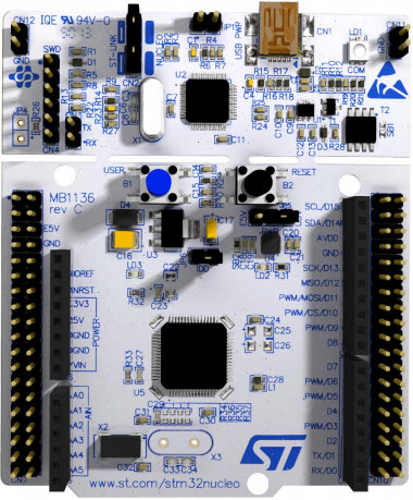
The STM32F446RE is available on the Nucleo-64 development board, which provides easy access to its pins. Below is a table summarizing the key pin functions:

Pin Name Function Description
PA0 GPIO, ADC_IN0, TIM2_CH1 General-purpose I/O, ADC input, Timer channel
PA1 GPIO, ADC_IN1, TIM2_CH2 General-purpose I/O, ADC input, Timer channel
PB6 GPIO, I2C1_SCL, TIM4_CH1 I2C clock line, Timer channel
PB7 GPIO, I2C1_SDA, TIM4_CH2 I2C data line, Timer channel
PC13 GPIO General-purpose I/O
PA9 GPIO, USART1_TX UART transmit pin
PA10 GPIO, USART1_RX UART receive pin
PA5 GPIO, SPI1_SCK SPI clock line
PA6 GPIO, SPI1_MISO SPI data input
PA7 GPIO, SPI1_MOSI SPI data output

For a complete pinout, refer to the STM32F446RE datasheet.

Usage Instructions

The STM32F446RE can be used in a variety of circuits and applications. Below are the steps and best practices for using this microcontroller:

Getting Started

  1. Power Supply: Ensure the microcontroller is powered with a voltage between 1.7V and 3.6V. If using the Nucleo-64 board, connect it via USB or an external power source.
  2. Programming Environment: Install an Integrated Development Environment (IDE) such as STM32CubeIDE or Keil uVision. Alternatively, you can use the Arduino IDE with the STM32 core installed.
  3. Flashing the Code: Use the onboard ST-LINK debugger/programmer to upload your code to the microcontroller.

Example: Blinking an LED

Below is an example of how to blink an LED connected to pin PA5 using the STM32F446RE and the Arduino IDE:

// Include the STM32 HAL library
#include <Arduino.h>

// Define the LED pin
#define LED_PIN PA5

void setup() {
  // Set the LED pin as an output
  pinMode(LED_PIN, OUTPUT);
}

void loop() {
  // Turn the LED on
  digitalWrite(LED_PIN, HIGH);
  delay(500); // Wait for 500 milliseconds

  // Turn the LED off
  digitalWrite(LED_PIN, LOW);
  delay(500); // Wait for 500 milliseconds
}

Important Considerations

  • Clock Configuration: Configure the system clock properly to achieve the desired performance. Use the STM32CubeMX tool to generate initialization code for clock settings.
  • Peripheral Initialization: Always initialize peripherals (e.g., UART, SPI, I2C) before using them in your application.
  • Debugging: Use the ST-LINK debugger for real-time debugging and troubleshooting.

Troubleshooting and FAQs

Common Issues

  1. Microcontroller Not Responding

    • Cause: Incorrect power supply or faulty connections.
    • Solution: Verify the power supply voltage and check all connections.
  2. Code Upload Fails

    • Cause: ST-LINK debugger not detected or incorrect settings in the IDE.
    • Solution: Ensure the ST-LINK driver is installed and the correct board is selected in the IDE.
  3. Peripherals Not Working

    • Cause: Peripheral not initialized or incorrect pin configuration.
    • Solution: Double-check the initialization code and pin assignments.

FAQs

  1. Can I use the STM32F446RE with the Arduino IDE?

    • Yes, the STM32F446RE is compatible with the Arduino IDE. Install the STM32 core to get started.
  2. What is the maximum clock speed of the STM32F446RE?

    • The maximum clock speed is 180 MHz.
  3. How do I configure the system clock?

    • Use the STM32CubeMX tool to generate clock configuration code or manually configure the RCC (Reset and Clock Control) registers.
  4. Can I use the STM32F446RE for motor control?

    • Yes, the STM32F446RE includes advanced control timers suitable for motor control applications.

By following this documentation, you can effectively use the STM32F446RE microcontroller in your projects. For more details, refer to the official datasheet and reference manual provided by STMicroelectronics.