How to Use Itsy Bitsy 32u4 3V @ 8MHz: Examples, Pinouts, and Specs
Introduction
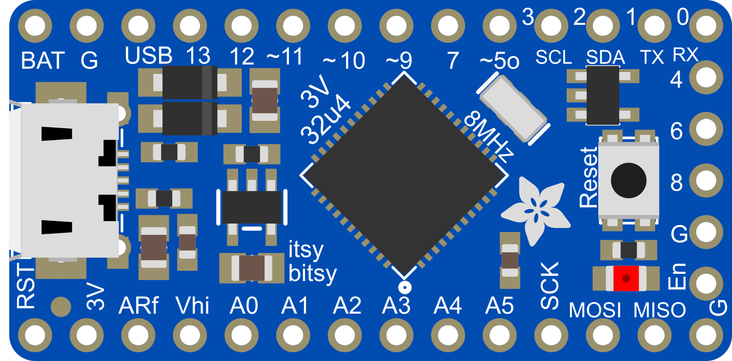
The Itsy Bitsy 32u4 3V @ 8MHz is a compact, high-performance microcontroller board based on the ATmega32u4. This board is designed for versatility and power in a small package, running at 3.3V and 8MHz. It is particularly suitable for low-power and battery-powered applications due to its energy-efficient design. The Itsy Bitsy 32u4 comes with a built-in USB interface, which allows for straightforward programming and communication with computers, without the need for an external USB-to-serial converter.
Explore Projects Built with Itsy Bitsy 32u4 3V @ 8MHz
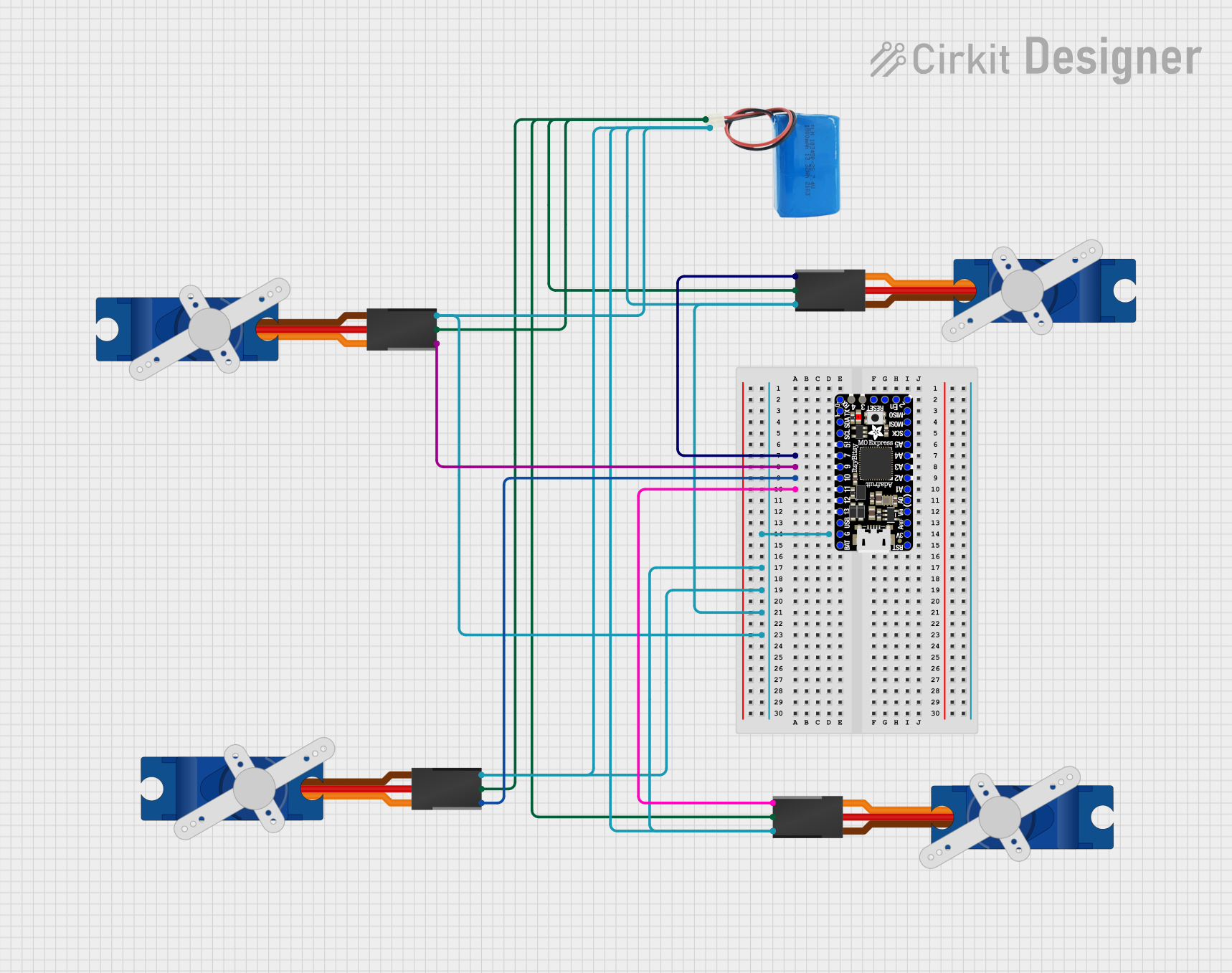
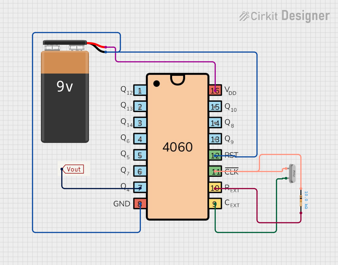

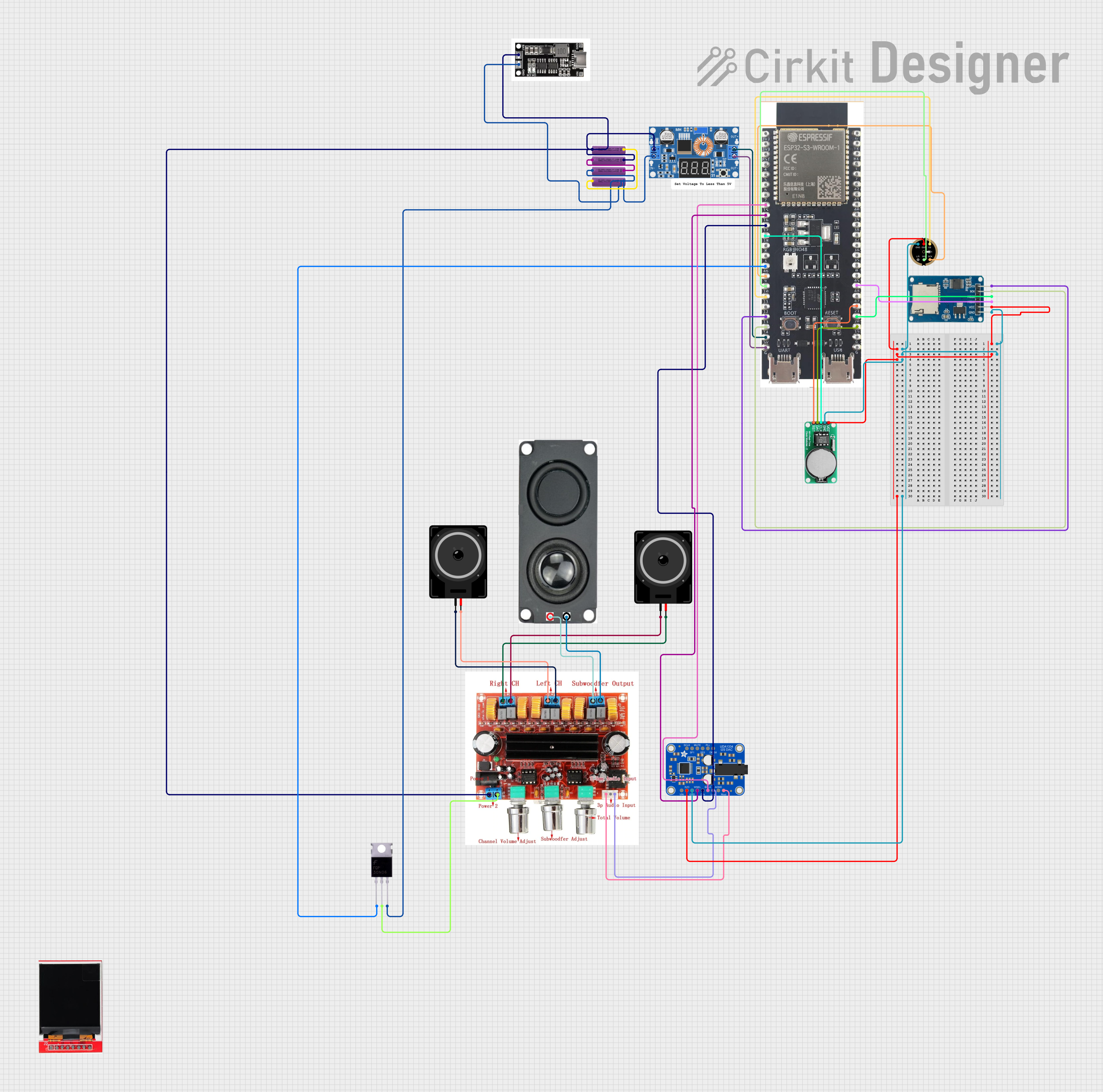
Explore Projects Built with Itsy Bitsy 32u4 3V @ 8MHz
Common Applications and Use Cases
- Wearable electronics
- Portable instruments
- Educational projects
- Prototyping IoT devices
- USB HID devices (keyboards, mice, game controllers)
Technical Specifications
Key Technical Details
- Microcontroller: ATmega32u4
- Operating Voltage: 3.3V
- Input Voltage: 3.3V-5V via VIN pin
- Clock Speed: 8MHz
- Digital I/O Pins: 20
- PWM Channels: 7
- Analog Input Channels: 12
- DC Current per I/O Pin: 40 mA
- Flash Memory: 32 KB (ATmega32u4) of which 4 KB used by bootloader
- SRAM: 2.5 KB (ATmega32u4)
- EEPROM: 1 KB (ATmega32u4)
- USB: Micro USB for programming and power
Pin Configuration and Descriptions
| Pin Number | Function | Description |
|---|---|---|
| 1 | GND | Ground |
| 2-7 | Digital I/O | Digital pins D0-D5 |
| 8-9 | XTAL1/XTAL2 | Crystal Oscillator |
| 10 | GND | Ground |
| 11-13 | Analog In | Analog pins A0-A2 |
| 14 | VCC | Positive Supply Voltage |
| 15 | RESET | Reset Pin |
| 16-21 | Digital I/O | Digital pins D6-D11 |
| 22-23 | Analog In | Analog pins A3-A4 |
| 24 | AREF | Analog Reference Voltage |
| 25 | GND | Ground |
| 26-31 | Digital I/O | Digital pins D12-D17 |
| 32 | VIN | Input Voltage for the board |
Usage Instructions
How to Use the Component in a Circuit
- Powering the Board: Connect a 3.3V power supply to the VIN pin, or power the board via the micro USB connection.
- Programming: Use the micro USB port to connect the Itsy Bitsy 32u4 to your computer. Select "Arduino Leonardo" in the Arduino IDE as the board type, since the ATmega32u4 is also used in the Leonardo and they share the same core functionality.
- Digital I/O: Utilize the digital pins for input or output by setting them up in your code using
pinMode(),digitalWrite(), anddigitalRead()functions. - Analog Input: Read analog voltages using the analog pins and the
analogRead()function. - PWM Output: Generate PWM signals on PWM-enabled pins using the
analogWrite()function.
Important Considerations and Best Practices
- Ensure that the power supply does not exceed 5V to avoid damaging the board.
- When connecting external components, consider the current limitations of the I/O pins.
- Use a current limiting resistor when driving LEDs or similar components.
- Avoid exposing the board to static electricity or physical stress.
Troubleshooting and FAQs
Common Issues
- Board not recognized by computer: Check the USB cable and port. Try a different cable or port if necessary.
- Sketch upload fails: Ensure the correct board (Arduino Leonardo) and port are selected in the Arduino IDE.
- Incorrect voltages at I/O pins: Verify that the board is powered correctly and that the pin modes are set correctly in the sketch.
Solutions and Tips for Troubleshooting
- Reset the board: Press the reset button on the board to restart the microcontroller.
- Double-check connections: Loose connections can cause unexpected behavior.
- Use external power: If the USB port cannot provide sufficient power, use an external power supply.
FAQs
Q: Can I use the Itsy Bitsy 32u4 with a 5V system? A: Yes, but you must ensure that all I/O pins are level-shifted to be compatible with 3.3V logic levels.
Q: How do I put the Itsy Bitsy 32u4 into bootloader mode? A: Double-tap the reset button quickly to enter bootloader mode, which allows you to upload new sketches.
Q: What is the maximum current the Itsy Bitsy 32u4 can draw from the USB port? A: The USB 2.0 specification limits the current to 500 mA, but the actual current draw should be kept significantly lower to ensure stability and avoid overheating.
Example Code for Arduino UNO
// Blink example for Itsy Bitsy 32u4 3V @ 8MHz
// The built-in LED is connected to pin 13 on the Itsy Bitsy 32u4.

void setup() {
  pinMode(13, OUTPUT); // Initialize the LED pin as an output
}

void loop() {
  digitalWrite(13, HIGH);   // Turn the LED on
  delay(1000);              // Wait for a second
  digitalWrite(13, LOW);    // Turn the LED off
  delay(1000);              // Wait for a second
}
Remember to select "Arduino Leonardo" as the board when uploading this code, as the Itsy Bitsy 32u4 shares the same microcontroller and is compatible with Leonardo board definitions.