Cirkit Designer
Your all-in-one circuit design IDE
Home /
Component Documentation
How to Use COMPONENTS 16 Relay board: Examples, Pinouts, and Specs
Introduction
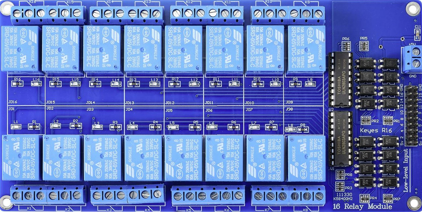
The TRU TC-9445344 16 Relay Board is a versatile electronic module designed to control up to 16 individual relays. Each relay can be independently triggered, enabling the control of multiple devices or circuits from a single control signal. This board is ideal for applications requiring high-voltage or high-current switching, such as home automation, industrial automation, and IoT projects.
Explore Projects Built with COMPONENTS 16 Relay board
ESP32-Powered Wi-Fi Controlled 8-Channel Relay Module

This circuit features an ESP32 microcontroller connected to an 8-channel relay module. The ESP32 controls the relay channels via its GPIO pins, allowing it to switch multiple external devices on and off. The ESP32 also provides power to the relay module.
ESP32-Based Smart Environment Controller with Relay and Sensor Integration
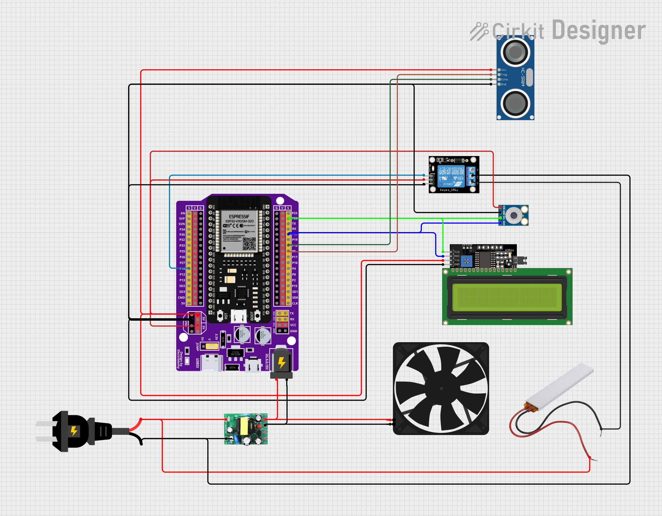
This circuit features an ESP32 microcontroller interfaced with various sensors and modules, including an MLX90614 infrared temperature sensor, an HC-SR04 ultrasonic distance sensor, and an LCD display for output. A KY-019 relay module is controlled by the ESP32 to switch an AC source, with a PTC for circuit protection. Additionally, an AC-to-DC converter powers the ESP32 and a fan, indicating the circuit may be used for temperature-based control applications with visual feedback and actuation capabilities.
ESP32-Controlled Smart Home Automation System with I2C LCD Feedback
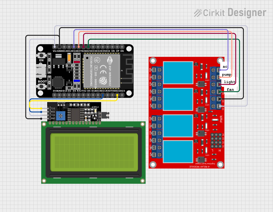
This circuit features an ESP32 microcontroller connected to a 4-channel relay module and a 20x4 LCD display with I2C interface. The ESP32 controls the relay channels to switch external devices and uses the LCD to display the status of each relay channel. The code includes Blynk IoT platform integration for remote control and monitoring, and the display provides a user interface for local status updates.
ESP32 and Arduino UNO Smart Relay Control with I2C LCD Display
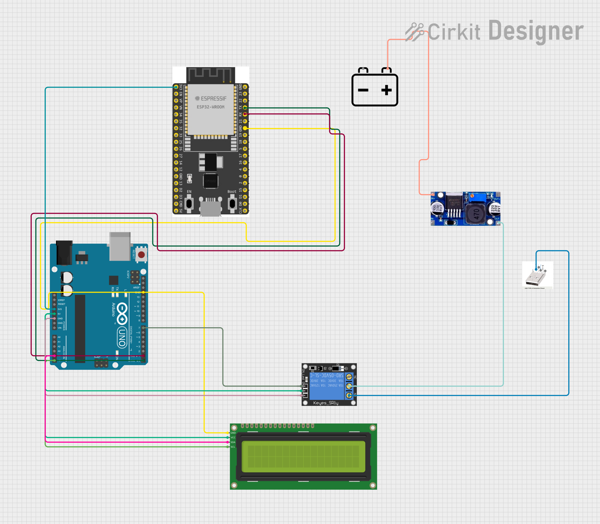
This circuit integrates an Arduino UNO and an ESP32 microcontroller to control a 1-channel relay and display information on a 16x2 I2C LCD. The relay is powered by a 12V battery through an LM2596 voltage regulator, and it can switch a USB port's D- line, while the LCD displays data received from the Arduino.
Explore Projects Built with COMPONENTS 16 Relay board
ESP32-Powered Wi-Fi Controlled 8-Channel Relay Module
This circuit features an ESP32 microcontroller connected to an 8-channel relay module. The ESP32 controls the relay channels via its GPIO pins, allowing it to switch multiple external devices on and off. The ESP32 also provides power to the relay module.
ESP32-Based Smart Environment Controller with Relay and Sensor Integration
This circuit features an ESP32 microcontroller interfaced with various sensors and modules, including an MLX90614 infrared temperature sensor, an HC-SR04 ultrasonic distance sensor, and an LCD display for output. A KY-019 relay module is controlled by the ESP32 to switch an AC source, with a PTC for circuit protection. Additionally, an AC-to-DC converter powers the ESP32 and a fan, indicating the circuit may be used for temperature-based control applications with visual feedback and actuation capabilities.
ESP32-Controlled Smart Home Automation System with I2C LCD Feedback
This circuit features an ESP32 microcontroller connected to a 4-channel relay module and a 20x4 LCD display with I2C interface. The ESP32 controls the relay channels to switch external devices and uses the LCD to display the status of each relay channel. The code includes Blynk IoT platform integration for remote control and monitoring, and the display provides a user interface for local status updates.
ESP32 and Arduino UNO Smart Relay Control with I2C LCD Display
This circuit integrates an Arduino UNO and an ESP32 microcontroller to control a 1-channel relay and display information on a 16x2 I2C LCD. The relay is powered by a 12V battery through an LM2596 voltage regulator, and it can switch a USB port's D- line, while the LCD displays data received from the Arduino.
Common Applications
- Home Automation: Control lights, fans, and other appliances remotely.
- Industrial Automation: Manage machinery, motors, and other high-power equipment.
- IoT Projects: Integrate with microcontrollers like Arduino or Raspberry Pi for smart control.
- Prototyping: Test and develop multi-channel switching systems.
Technical Specifications
Key Technical Details
- Manufacturer: TRU
- Part ID: TC-9445344
- Number of Relays: 16
- Relay Type: Electromechanical
- Operating Voltage: 5V DC (control signal)
- Relay Output Voltage: Up to 250V AC or 30V DC
- Relay Output Current: Up to 10A per channel
- Trigger Type: Active low
- Isolation: Optocoupler isolation for each relay
- Dimensions: 190mm x 90mm x 20mm
- Mounting: Screw holes for secure installation
- Connector Type: Screw terminals for load connections, pin headers for control signals
Pin Configuration and Descriptions
Control Signal Pins
| Pin Number | Label | Description |
|---|---|---|
| 1-16 | IN1-IN16 | Control signals for relays 1 to 16 (active low) |
| 17 | GND | Ground connection for the control circuit |
| 18 | VCC | 5V DC power supply for the control circuit |
Relay Output Terminals
| Terminal Group | Label | Description |
|---|---|---|
| 1-16 | COM1-COM16 | Common terminal for relays 1 to 16 |
| 1-16 | NO1-NO16 | Normally Open terminal for relays 1 to 16 |
| 1-16 | NC1-NC16 | Normally Closed terminal for relays 1 to 16 |
Usage Instructions
How to Use the Component in a Circuit
- Power the Board: Connect a 5V DC power supply to the
VCCandGNDpins. - Connect the Control Signals: Use a microcontroller (e.g., Arduino) to send control signals to the
IN1-IN16pins. Each pin corresponds to a specific relay. - Connect the Load: Attach the devices or circuits you want to control to the relay output terminals (
COM,NO,NC).- Use the
NO(Normally Open) terminal if you want the circuit to be off by default. - Use the
NC(Normally Closed) terminal if you want the circuit to be on by default.
- Use the
- Trigger the Relays: Send a LOW signal (0V) to the desired
INpin to activate the corresponding relay.
Important Considerations and Best Practices
- Power Supply: Ensure the power supply can provide sufficient current for all 16 relays. Each relay may draw up to 70mA when activated.
- Isolation: The optocoupler isolation protects the control circuit from high-voltage spikes. Ensure proper grounding to maintain isolation.
- Load Ratings: Do not exceed the maximum voltage (250V AC or 30V DC) or current (10A) ratings for each relay.
- Heat Management: If multiple relays are activated simultaneously, ensure adequate ventilation to prevent overheating.
Example: Connecting to an Arduino UNO
Below is an example of how to control the first relay using an Arduino UNO:
// Example code to control the first relay on the TRU TC-9445344 16 Relay Board
// Ensure the relay board is powered with 5V and connected to the Arduino

#define RELAY1_PIN 2  // Connect IN1 of the relay board to Arduino pin 2

void setup() {
  pinMode(RELAY1_PIN, OUTPUT);  // Set the relay control pin as an output
  digitalWrite(RELAY1_PIN, HIGH);  // Keep the relay off initially (active low)
}

void loop() {
  digitalWrite(RELAY1_PIN, LOW);  // Turn the relay ON
  delay(1000);  // Wait for 1 second
  digitalWrite(RELAY1_PIN, HIGH);  // Turn the relay OFF
  delay(1000);  // Wait for 1 second
}
Troubleshooting and FAQs
Common Issues and Solutions
Relays Not Activating
- Cause: Insufficient power supply.
- Solution: Ensure the power supply provides at least 5V and sufficient current for all active relays.
Control Signals Not Working
- Cause: Incorrect wiring or signal levels.
- Solution: Verify the control signal connections and ensure the microcontroller outputs a LOW signal to activate the relays.
Load Not Switching
- Cause: Incorrect wiring of the load to the relay terminals.
- Solution: Double-check the connections to the
COM,NO, andNCterminals.
Overheating
- Cause: Too many relays activated simultaneously or high current loads.
- Solution: Reduce the number of active relays or use external cooling methods.
FAQs
- Can I use a 3.3V microcontroller with this board?
- Yes, but you may need a level shifter to ensure proper triggering of the relays.
- What happens if I exceed the load ratings?
- Exceeding the load ratings can damage the relays or cause unsafe operation. Always stay within the specified limits.
- Can I control AC and DC loads simultaneously?
- Yes, as long as each relay's load does not exceed its voltage and current ratings.
This concludes the documentation for the TRU TC-9445344 16 Relay Board.