How to Use ESP32 S3: Examples, Pinouts, and Specs
Introduction
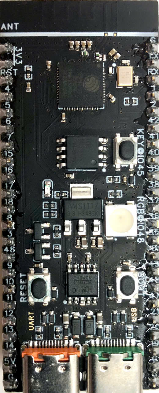
The ESP32 S3 DEVKITC-1 by WeAct Studio is a powerful microcontroller designed for IoT applications. It integrates Wi-Fi and Bluetooth capabilities, making it ideal for a wide range of wireless communication projects. The ESP32 S3 features a dual-core processor, ample memory, and a variety of peripherals, providing versatile connectivity and control options.
Explore Projects Built with ESP32 S3


Explore Projects Built with ESP32 S3
Common Applications and Use Cases
- Home Automation: Control and monitor home appliances remotely.
- Wearable Devices: Develop smart wearable gadgets with wireless connectivity.
- Industrial Automation: Implement IoT solutions for industrial monitoring and control.
- Smart Agriculture: Monitor and manage agricultural environments.
- Health Monitoring: Create devices for remote health monitoring and data collection.
Technical Specifications
Key Technical Details
| Specification | Value |
|---|---|
| Processor | Dual-core Xtensa LX7 |
| Clock Speed | Up to 240 MHz |
| Flash Memory | 8 MB |
| SRAM | 512 KB |
| Wi-Fi | 802.11 b/g/n |
| Bluetooth | Bluetooth 5.0 LE |
| Operating Voltage | 3.3V |
| Input Voltage | 5V (via USB) |
| GPIO Pins | 34 |
| ADC Channels | 18 (12-bit ADC) |
| DAC Channels | 2 (8-bit DAC) |
| Communication | UART, SPI, I2C, I2S, CAN, Ethernet MAC |
| USB | USB OTG |
| Power Consumption | Ultra-low power consumption in deep sleep |
Pin Configuration and Descriptions
| Pin Number | Pin Name | Description |
|---|---|---|
| 1 | GND | Ground |
| 2 | 3V3 | 3.3V Power Output |
| 3 | EN | Enable Pin |
| 4 | IO0 | GPIO0, Boot Mode Selection |
| 5 | IO1 | GPIO1, UART0 TX |
| 6 | IO2 | GPIO2, ADC2 Channel 2 |
| 7 | IO3 | GPIO3, UART0 RX |
| 8 | IO4 | GPIO4, ADC2 Channel 0 |
| 9 | IO5 | GPIO5, ADC2 Channel 1 |
| 10 | IO6 | GPIO6, SPI Flash SCK |
| 11 | IO7 | GPIO7, SPI Flash MISO |
| 12 | IO8 | GPIO8, SPI Flash MOSI |
| 13 | IO9 | GPIO9, SPI Flash CS |
| 14 | IO10 | GPIO10, UART1 TX |
| 15 | IO11 | GPIO11, UART1 RX |
| 16 | IO12 | GPIO12, ADC2 Channel 5 |
| 17 | IO13 | GPIO13, ADC2 Channel 4 |
| 18 | IO14 | GPIO14, ADC2 Channel 6 |
| 19 | IO15 | GPIO15, ADC2 Channel 3 |
| 20 | IO16 | GPIO16, UART2 TX |
| 21 | IO17 | GPIO17, UART2 RX |
| 22 | IO18 | GPIO18, I2C SCL |
| 23 | IO19 | GPIO19, I2C SDA |
| 24 | IO20 | GPIO20, SPI SCK |
| 25 | IO21 | GPIO21, SPI MISO |
| 26 | IO22 | GPIO22, SPI MOSI |
| 27 | IO23 | GPIO23, SPI CS |
| 28 | IO24 | GPIO24, ADC2 Channel 7 |
| 29 | IO25 | GPIO25, DAC1 |
| 30 | IO26 | GPIO26, DAC2 |
| 31 | IO27 | GPIO27, ADC2 Channel 8 |
| 32 | IO28 | GPIO28, ADC2 Channel 9 |
| 33 | IO29 | GPIO29, ADC2 Channel 10 |
| 34 | IO30 | GPIO30, ADC2 Channel 11 |
| 35 | IO31 | GPIO31, ADC2 Channel 12 |
| 36 | IO32 | GPIO32, ADC2 Channel 13 |
| 37 | IO33 | GPIO33, ADC2 Channel 14 |
| 38 | IO34 | GPIO34, ADC2 Channel 15 |
| 39 | IO35 | GPIO35, ADC2 Channel 16 |
| 40 | IO36 | GPIO36, ADC2 Channel 17 |
| 41 | IO37 | GPIO37, ADC2 Channel 18 |
| 42 | IO38 | GPIO38, ADC2 Channel 19 |
| 43 | IO39 | GPIO39, ADC2 Channel 20 |
Usage Instructions
How to Use the Component in a Circuit
Powering the ESP32 S3:
- Connect the 5V pin to a 5V power source (e.g., USB).
- Ensure the GND pin is connected to the ground of the power source.
Programming the ESP32 S3:
- Use a USB cable to connect the ESP32 S3 to your computer.
- Install the necessary drivers and the ESP32 board package in the Arduino IDE.
- Select the appropriate board and port in the Arduino IDE.
Basic Circuit Example:
- Connect an LED to GPIO2 (IO2) with a current-limiting resistor.
- Use the following code to blink the LED:
// Define the LED pin
const int ledPin = 2;

void setup() {
  // Initialize the LED pin as an output
  pinMode(ledPin, OUTPUT);
}

void loop() {
  // Turn the LED on
  digitalWrite(ledPin, HIGH);
  delay(1000); // Wait for a second

  // Turn the LED off
  digitalWrite(ledPin, LOW);
  delay(1000); // Wait for a second
}
Important Considerations and Best Practices
- Voltage Levels: Ensure that the input voltage does not exceed 5V to avoid damaging the board.
- Pin Usage: Be mindful of the pin functions and avoid conflicts, especially with pins used for boot mode selection.
- Power Consumption: Utilize deep sleep modes to reduce power consumption in battery-powered applications.
- Antenna Placement: Ensure proper placement of the ESP32 S3 to avoid interference with the Wi-Fi and Bluetooth antennas.
Troubleshooting and FAQs
Common Issues Users Might Face
ESP32 S3 Not Detected by Computer:
- Ensure the USB cable is properly connected and functional.
- Install the correct drivers for the ESP32 S3.
Upload Errors in Arduino IDE:
- Check the selected board and port in the Arduino IDE.
- Press the EN (Enable) button on the ESP32 S3 before uploading.
Wi-Fi Connection Issues:
- Verify the Wi-Fi credentials and ensure the network is within range.
- Check for interference from other devices.
Solutions and Tips for Troubleshooting
Resetting the ESP32 S3:
- Press the EN button to reset the board if it becomes unresponsive.
Debugging with Serial Monitor:
- Use the Serial Monitor in the Arduino IDE to print debug messages and monitor the ESP32 S3's behavior.
Checking Power Supply:
- Ensure a stable power supply, especially when using peripherals that draw significant current.
Firmware Updates:
- Keep the ESP32 S3 firmware updated to benefit from the latest features and bug fixes.
By following this documentation, users can effectively utilize the ESP32 S3 DEVKITC-1 for a variety of IoT applications, ensuring reliable performance and ease of use.