
How to Use Arduino Due (Rev2b): Examples, Pinouts, and Specs
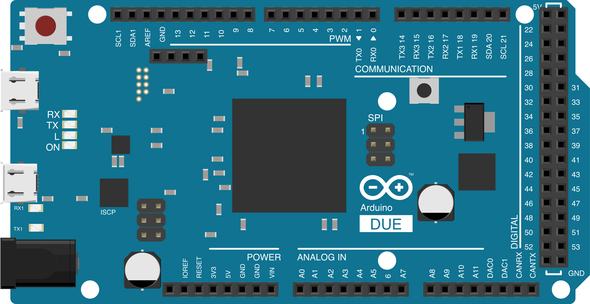
 Design with Arduino Due (Rev2b) in Cirkit Designer
Introduction
The Arduino Due (Rev2b) is a high-performance microcontroller board based on the Atmel SAM3X8E ARM Cortex-M3 processor. It is designed for applications requiring significant processing power, such as robotics, data acquisition, and advanced control systems. The board features 54 digital input/output pins (12 of which can be used as PWM outputs), 12 analog inputs, 2 DAC outputs, and USB host capabilities. Its 32-bit architecture allows for faster computation and more complex operations compared to 8-bit Arduino boards.
Explore Projects Built with Arduino Due (Rev2b)
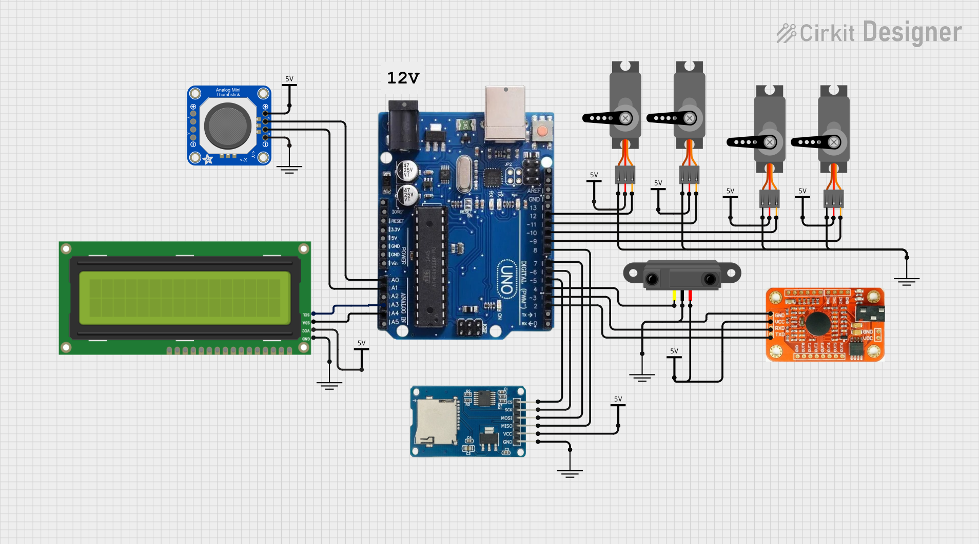 Open Project in Cirkit Designer
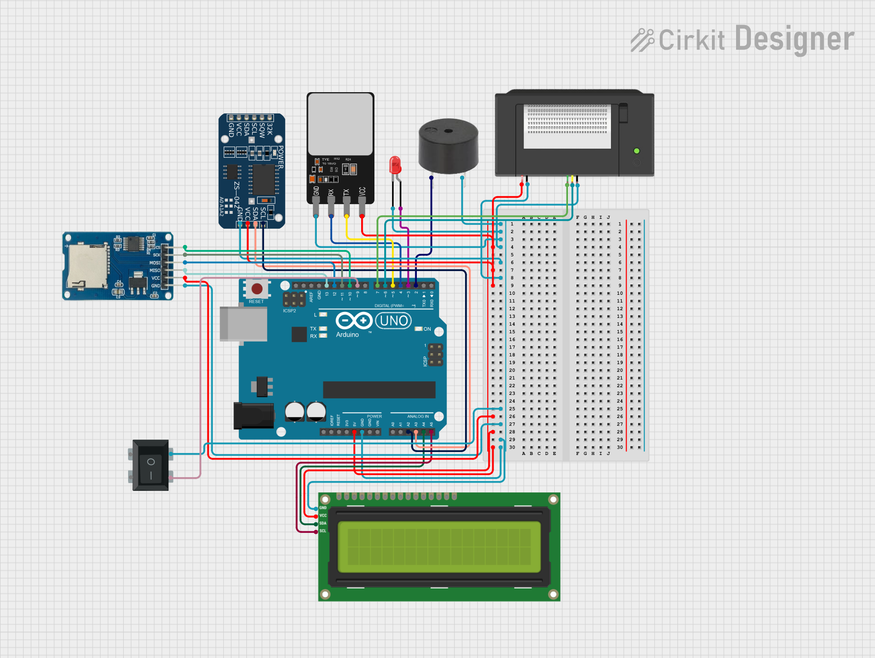 Open Project in Cirkit Designer
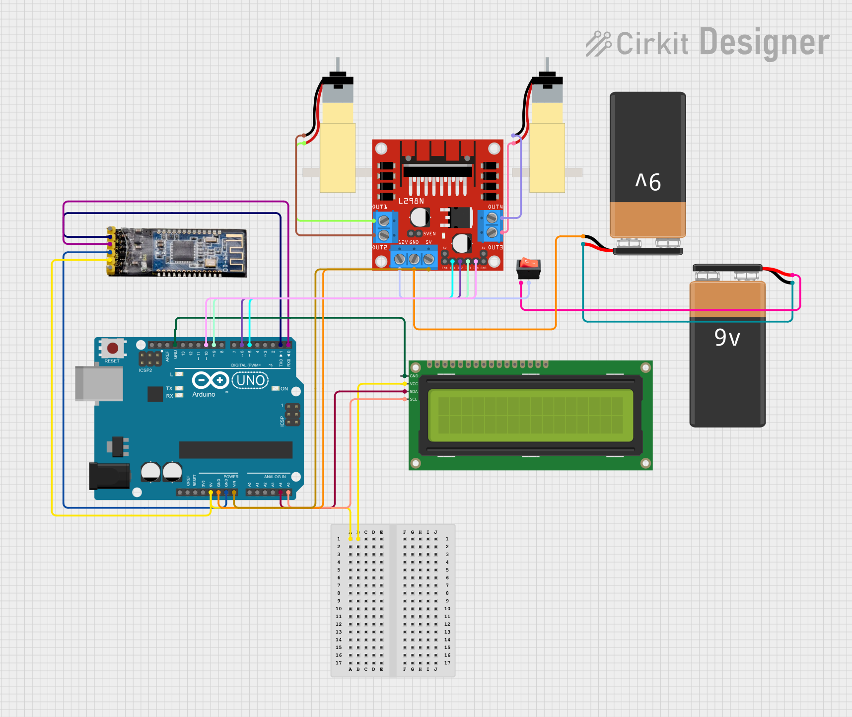 Open Project in Cirkit Designer
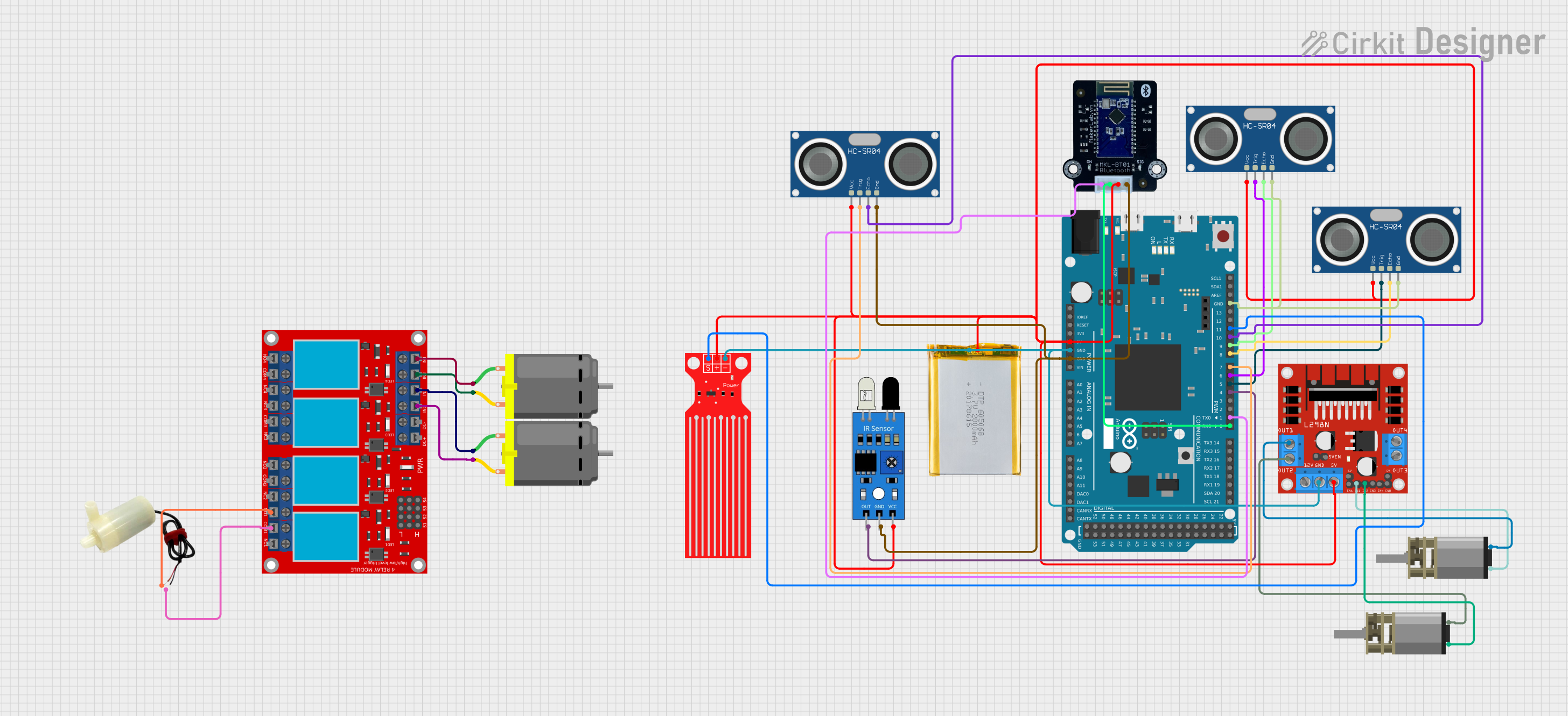 Open Project in Cirkit Designer
Explore Projects Built with Arduino Due (Rev2b)
Open Project in Cirkit DesignerOpen Project in Cirkit DesignerOpen Project in Cirkit DesignerOpen Project in Cirkit DesignerCommon Applications and Use Cases
- Robotics and automation systems
- Data logging and real-time data processing
- Audio signal processing
- Advanced motor control
- IoT (Internet of Things) applications
- High-speed communication systems
Technical Specifications
Key Technical Details
| Specification | Value |
|---|---|
| Microcontroller | Atmel SAM3X8E ARM Cortex-M3 |
| Operating Voltage | 3.3V |
| Input Voltage (recommended) | 7-12V |
| Input Voltage (limits) | 6-16V |
| Digital I/O Pins | 54 (12 PWM outputs) |
| Analog Input Pins | 12 |
| Analog Output Pins (DAC) | 2 |
| DC Current per I/O Pin | 130 mA |
| Flash Memory | 512 KB |
| SRAM | 96 KB |
| Clock Speed | 84 MHz |
| USB Host Capability | Yes |
| Dimensions | 101.52 mm x 53.3 mm |
Pin Configuration and Descriptions
Digital Pins
| Pin Number | Functionality |
|---|---|
| 0-53 | General-purpose digital I/O pins |
| 2-13 | PWM output pins |
| 50-53 | SPI communication pins |
Analog Pins
| Pin Number | Functionality |
|---|---|
| A0-A11 | Analog input pins (12-bit resolution) |
Power Pins
| Pin Name | Description |
|---|---|
| VIN | Input voltage to the board (7-12V) |
| 3.3V | Regulated 3.3V output |
| 5V | Regulated 5V output |
| GND | Ground |
Communication Pins
| Pin Name | Description |
|---|---|
| TX/RX | UART communication pins |
| SDA/SCL | I2C communication pins |
| SPI | SPI communication pins (50-53) |
| CANRX/CANTX | CAN bus communication pins |
Usage Instructions
How to Use the Arduino Due in a Circuit
Powering the Board:
- Use the VIN pin or the DC power jack to supply 7-12V to the board.
- Alternatively, power the board via the USB port (5V).
Connecting Components:
- Use the digital I/O pins for interfacing with sensors, actuators, and other peripherals.
- For analog sensors, connect them to the analog input pins (A0-A11).
- Use the PWM pins (2-13) for applications requiring variable voltage output, such as motor control.
Programming the Board:
- Connect the Arduino Due to your computer using a micro-USB cable.
- Open the Arduino IDE, select "Arduino Due (Programming Port)" under the Tools > Board menu.
- Write your code and upload it to the board.
Using USB Host Capability:
- Connect USB devices (e.g., keyboards, mice) to the USB host port.
- Use the USBHost library in the Arduino IDE to interact with connected devices.
Important Considerations and Best Practices
- Voltage Levels: The Arduino Due operates at 3.3V logic levels. Applying 5V to its pins can damage the board. Use level shifters if interfacing with 5V devices.
- Power Supply: Ensure the input voltage does not exceed the recommended range (7-12V) to avoid damaging the board.
- Programming Ports: Use the "Programming Port" for uploading sketches and debugging. The "Native USB Port" can be used for USB communication and advanced features.
Example Code: Blinking an LED
// This example demonstrates how to blink an LED connected to pin 13
// on the Arduino Due. The LED will turn on for 1 second and off for 1 second.

void setup() {
  pinMode(13, OUTPUT); // Set pin 13 as an output pin
}

void loop() {
  digitalWrite(13, HIGH); // Turn the LED on
  delay(1000);            // Wait for 1 second
  digitalWrite(13, LOW);  // Turn the LED off
  delay(1000);            // Wait for 1 second
}
Troubleshooting and FAQs
Common Issues and Solutions
The board is not recognized by the computer:
- Ensure the correct USB cable is used (data-capable, not power-only).
- Check that the correct port is selected in the Arduino IDE under Tools > Port.
- Try using the "Programming Port" instead of the "Native USB Port."
Sketch upload fails:
- Verify that the correct board ("Arduino Due (Programming Port)") is selected in the Arduino IDE.
- Press the "Erase" button on the board, followed by the "Reset" button, and try uploading again.
Components not working as expected:
- Double-check wiring and connections.
- Ensure components are compatible with the 3.3V logic level of the Arduino Due.
- Use pull-up or pull-down resistors where necessary.
Board overheating:
- Ensure the input voltage does not exceed 12V.
- Avoid drawing excessive current from the I/O pins (maximum 130 mA per pin).
FAQs
Can I use shields designed for 5V Arduino boards?
Yes, but you must ensure the shield is compatible with 3.3V logic levels or use level shifters.What is the difference between the Programming Port and the Native USB Port?
The Programming Port is used for uploading sketches and debugging, while the Native USB Port supports USB communication and advanced features like USB OTG.Can I power the board using only the USB port?
Yes, the board can be powered via the USB port, but ensure the connected USB device can supply sufficient current.How do I reset the board?
Press the "Reset" button on the board to restart the microcontroller.