
How to Use IDC24: Examples, Pinouts, and Specs
 Design with IDC24 in Cirkit Designer
Introduction
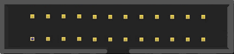
The IDC24 (Insulation Displacement Connector, 24-pin) is a versatile and widely used connector designed for efficient and reliable interfacing of electronic components. It features 24 pins, making it suitable for transmitting both power and signals in a compact form factor. The IDC24 is commonly used in ribbon cable assemblies, enabling quick and secure connections in a variety of applications.
Explore Projects Built with IDC24
 Open Project in Cirkit Designer
 Open Project in Cirkit Designer
 Open Project in Cirkit Designer
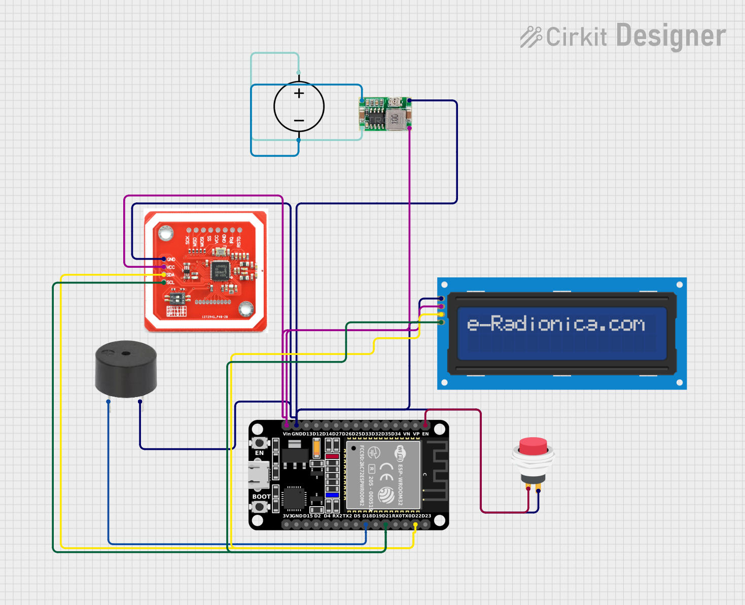 Open Project in Cirkit Designer
Explore Projects Built with IDC24
Open Project in Cirkit DesignerOpen Project in Cirkit DesignerOpen Project in Cirkit DesignerOpen Project in Cirkit DesignerCommon Applications and Use Cases
- Microcontroller and peripheral interfacing: Connecting microcontrollers to sensors, displays, or other modules.
- Data transmission: Used in communication systems for transmitting signals between devices.
- Power distribution: Provides a reliable interface for distributing power in electronic circuits.
- Prototyping and development: Ideal for breadboards and development boards due to its ease of use.
- Industrial equipment: Found in control panels and machinery for signal and power connections.
Technical Specifications
Key Technical Details
| Parameter | Value |
|---|---|
| Number of Pins | 24 |
| Connector Type | Insulation Displacement (IDC) |
| Pitch | 2.54 mm (0.1 inch) |
| Current Rating | 1 A per pin |
| Voltage Rating | 250 V AC/DC |
| Operating Temperature | -40°C to +105°C |
| Contact Resistance | ≤ 20 mΩ |
| Insulation Resistance | ≥ 1000 MΩ |
| Durability | 500 mating cycles |
Pin Configuration and Descriptions
The IDC24 connector has 24 pins arranged in two rows of 12 pins each. The pinout is typically as follows:
| Pin Number | Description | Notes |
|---|---|---|
| 1 | Signal/Power Line 1 | Can be used for power or signal |
| 2 | Ground | Common ground connection |
| 3 | Signal/Power Line 2 | |
| 4 | Ground | |
| ... | ... | |
| 23 | Signal/Power Line 12 | |
| 24 | Ground |
Note: The exact pin configuration may vary depending on the application. Always refer to the specific circuit design or datasheet for proper pin assignments.
Usage Instructions
How to Use the IDC24 in a Circuit
Prepare the Ribbon Cable:
- Use a 24-wire ribbon cable with a 2.54 mm pitch to match the IDC24 connector.
- Ensure the cable length is appropriate for your application to minimize signal loss.
Attach the Connector:
- Align the ribbon cable with the IDC24 connector, ensuring proper orientation.
- Use a crimping tool or a bench press to securely attach the connector to the cable.
Connect to the Circuit:
- Plug the IDC24 connector into the corresponding header or socket on your circuit board.
- Verify that the pins are aligned correctly to avoid short circuits or damage.
Secure the Connection:
- If necessary, use a strain relief clip to prevent the cable from being accidentally pulled out.
Important Considerations and Best Practices
- Pin Mapping: Double-check the pin mapping to ensure proper connections for power and signals.
- Current and Voltage Ratings: Do not exceed the specified current (1 A per pin) or voltage (250 V AC/DC) ratings.
- Cable Length: Keep ribbon cable lengths as short as possible to reduce signal degradation.
- Environmental Conditions: Ensure the operating temperature and humidity are within the specified range.
- Mating Cycles: Avoid excessive plugging/unplugging to maintain the connector's durability.
Example: Connecting IDC24 to an Arduino UNO
The IDC24 can be used to connect multiple sensors or modules to an Arduino UNO. Below is an example of how to interface an IDC24 connector with an Arduino:
// Example: Reading data from a sensor connected via IDC24 to Arduino UNO

// Define the pin connected to the sensor's output
const int sensorPin = A0; // Analog pin A0 is used for the sensor

void setup() {
  Serial.begin(9600); // Initialize serial communication at 9600 baud
  pinMode(sensorPin, INPUT); // Set the sensor pin as input
}

void loop() {
  int sensorValue = analogRead(sensorPin); // Read the sensor value
  Serial.print("Sensor Value: ");
  Serial.println(sensorValue); // Print the sensor value to the Serial Monitor
  delay(500); // Wait for 500 ms before the next reading
}
Note: Ensure the sensor's output pin is correctly mapped to the IDC24 pin connected to
A0on the Arduino.
Troubleshooting and FAQs
Common Issues and Solutions
Loose Connections:
- Issue: The IDC24 connector is not securely attached to the ribbon cable or header.
- Solution: Re-crimp the connector using a proper crimping tool and ensure alignment.
Signal Interference:
- Issue: Noise or interference in the transmitted signals.
- Solution: Use shorter ribbon cables and consider shielding the cable if interference persists.
Overheating:
- Issue: The connector or cable becomes warm during operation.
- Solution: Check the current draw and ensure it does not exceed 1 A per pin. Distribute the load across multiple pins if necessary.
Incorrect Pin Mapping:
- Issue: Components do not function as expected.
- Solution: Verify the pin mapping and ensure the connections match the circuit design.
FAQs
Q: Can the IDC24 handle high-frequency signals?
A: Yes, but for high-frequency signals, ensure the cable length is minimized to reduce signal degradation.Q: Is the IDC24 connector reusable?
A: While it is possible to reuse the connector, it is not recommended as the contacts may degrade after removal.Q: Can I use the IDC24 for power distribution?
A: Yes, but ensure the current does not exceed 1 A per pin and distribute the load across multiple pins if needed.Q: How do I identify pin 1 on the IDC24 connector?
A: Pin 1 is typically marked with a small triangle or a red stripe on the ribbon cable.
By following this documentation, you can effectively use the IDC24 connector in your electronic projects while ensuring reliable performance and durability.