How to Use Adafruit Feather nRF52840: Examples, Pinouts, and Specs
Introduction
The Adafruit Feather nRF52840 is a versatile and compact development board that harnesses the power of the Nordic Semiconductor nRF52840 System-on-Chip (SoC). This board is part of the Feather ecosystem, known for its portable and modular design. With an ARM Cortex-M4 CPU, built-in Bluetooth Low Energy (BLE), and a rich set of peripherals, the Feather nRF52840 is ideal for Internet of Things (IoT) projects, wearable devices, and wireless applications.
Explore Projects Built with Adafruit Feather nRF52840

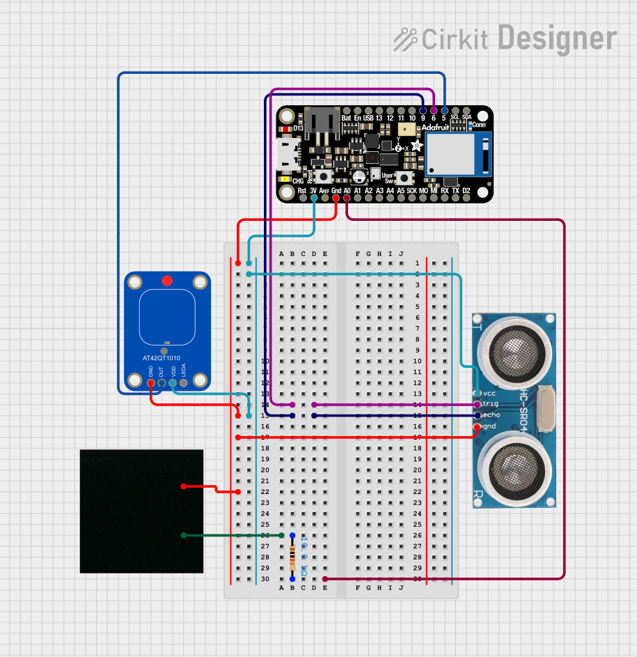
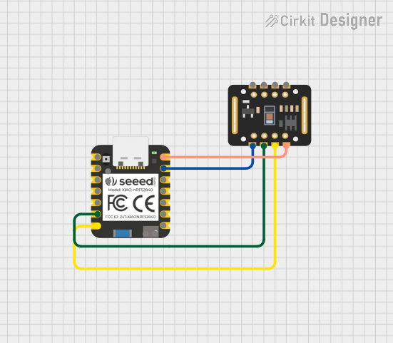

Explore Projects Built with Adafruit Feather nRF52840
Common Applications and Use Cases
- Wearable electronics
- Wireless sensor networks
- IoT connected devices
- Bluetooth-enabled products
- Prototyping for embedded systems
Technical Specifications
Key Technical Details
- Microcontroller: Nordic nRF52840 SoC
- CPU: 32-bit ARM Cortex-M4 with FPU
- Clock Speed: 64 MHz
- Flash Memory: 1 MB
- SRAM: 256 KB
- Bluetooth: BLE 5.0
- I/O Pins: 21 GPIO pins
- Voltage Supply: 3.3V regulator with 1A peak current output
- Battery: Li-Po single cell, 3.7V, 2-pin JST-PH connector
- USB: Native USB support with USB bootloader and serial port debugging
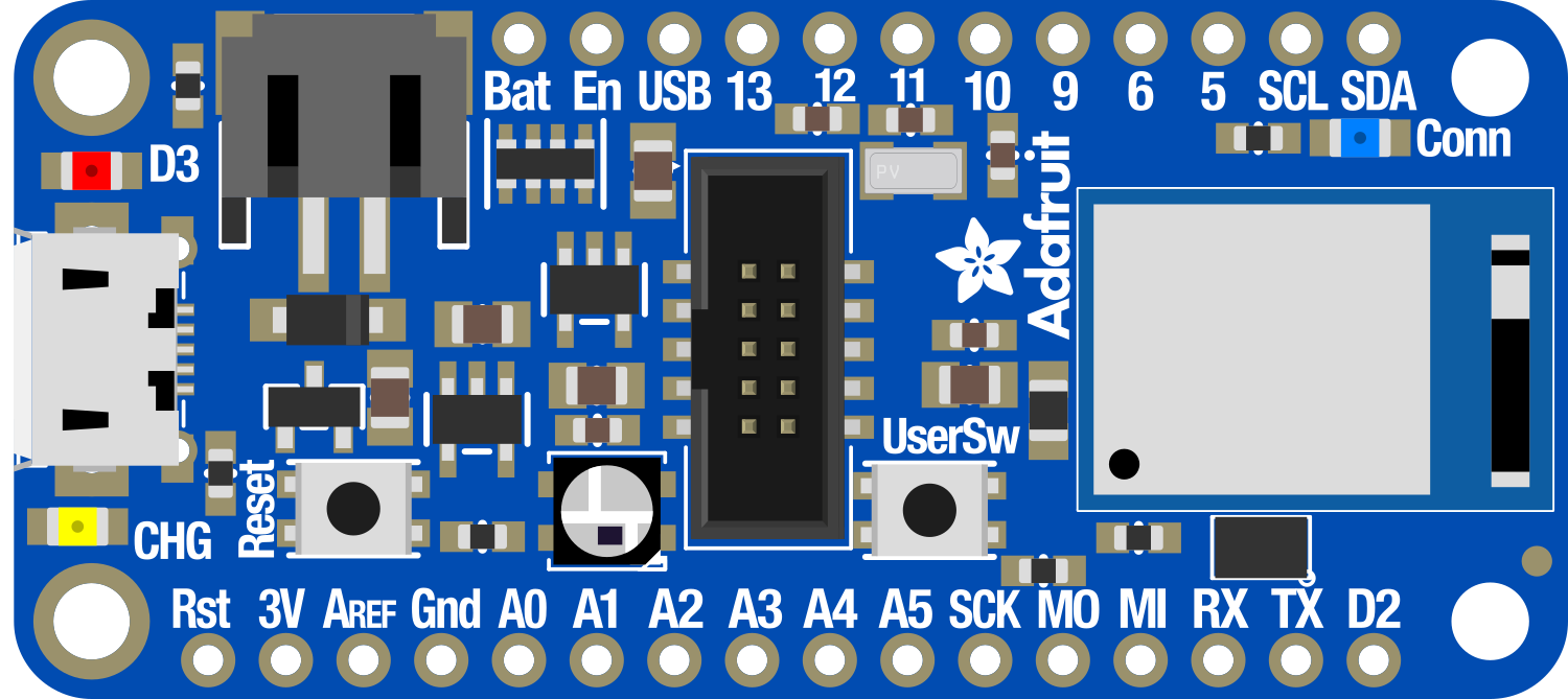
Pin Configuration and Descriptions
| Pin Number | Function | Description |
|---|---|---|
| 1 | GND | Ground |
| 2 | 3V3 | 3.3V power supply output |
| 3-8 | Analog Inputs | A0-A5, can also be used as digital I/O |
| 9-10 | I2C Interface | SDA (data line) and SCL (clock line) |
| 11-12 | SPI Interface | MISO (Master In Slave Out), MOSI (Master Out Slave In) |
| 13 | SPI Interface | SCK (Serial Clock) |
| 14-19 | Digital I/O | D5-D10, can be used for digital input/output |
| 20 | RX | UART receive pin |
| 21 | TX | UART transmit pin |
Usage Instructions
How to Use the Component in a Circuit
Powering the Board:
- You can power the Feather nRF52840 via USB or through the JST-PH battery connector.
- Ensure that the power supply is within the recommended voltage range.
Connecting Peripherals:
- Use the GPIO pins to connect sensors, actuators, or other modules.
- For I2C devices, connect SDA and SCL pins accordingly.
- For SPI communication, use MISO, MOSI, and SCK pins.
Programming the Board:
- The board can be programmed using the Arduino IDE or other development environments that support the nRF52840.
- Select the appropriate board from the tools menu in the Arduino IDE.
Important Considerations and Best Practices
- Always disconnect the board from power sources before making or altering connections.
- Use a current limiting resistor when connecting LEDs to GPIO pins.
- When using the board's Bluetooth functionality, ensure compliance with local regulations regarding wireless transmission.
- Avoid exposing the board to static electricity or physical stress.
Troubleshooting and FAQs
Common Issues Users Might Face
Board Not Recognized by Computer:
- Ensure the USB cable is properly connected and functional.
- Check that the correct drivers are installed on your computer.
Failure to Upload Sketches:
- Verify the correct board and port are selected in the Arduino IDE.
- Press the reset button on the board twice quickly to enter bootloader mode if necessary.
Bluetooth Connectivity Issues:
- Ensure the BLE stack and libraries are correctly configured in your development environment.
- Check the antenna and ensure there's no physical obstruction or interference.
Solutions and Tips for Troubleshooting
- If the board is not recognized, try using a different USB port or cable.
- For upload failures, double-check the code for errors and ensure the bootloader is up to date.
- For Bluetooth issues, test with a simple BLE example to isolate the problem.
Example Code for Arduino UNO
Here's a simple example of how to blink an LED using the Adafruit Feather nRF52840 with the Arduino IDE:
// Define the LED pin
#define LED_PIN 13

void setup() {
  // Initialize the LED pin as an output
  pinMode(LED_PIN, OUTPUT);
}

void loop() {
  // Turn the LED on
  digitalWrite(LED_PIN, HIGH);
  // Wait for 1 second
  delay(1000);
  // Turn the LED off
  digitalWrite(LED_PIN, LOW);
  // Wait for 1 second
  delay(1000);
}
Remember to select the Adafruit Feather nRF52840 board from the Arduino IDE before uploading the sketch.
Note: This code is for demonstration purposes and assumes the use of the onboard LED connected to pin 13. If you're using an external LED, ensure it's connected with a suitable current-limiting resistor.