How to Use 74LS245: Examples, Pinouts, and Specs
Introduction
The 74LS245 is a high-speed, low-power octal bus transceiver manufactured by Texas Instruments. It is designed to allow bidirectional data transmission between two buses, making it ideal for applications requiring data buffering or bus interfacing. The device features three-state outputs, enabling multiple devices to share the same bus without interference. Its robust design ensures reliable operation in digital systems.
Explore Projects Built with 74LS245


Explore Projects Built with 74LS245
Common Applications and Use Cases
- Microcontroller and microprocessor bus interfacing
- Memory address/data bus buffering
- Bidirectional data transfer in digital systems
- Signal isolation and level shifting
- Multiplexed data communication
Technical Specifications
Key Technical Details
- Supply Voltage (Vcc): 4.75V to 5.25V
- Input Voltage (VI): 0V to 7V
- Output Voltage (VO): 0V to 5.5V
- High-Level Input Current (IIH): 20 µA (max)
- Low-Level Input Current (IIL): -0.4 mA (max)
- Output Current (IO): ±24 mA
- Propagation Delay (tpd): 12 ns (typical)
- Operating Temperature Range: 0°C to 70°C
- Power Dissipation: 500 mW (max)
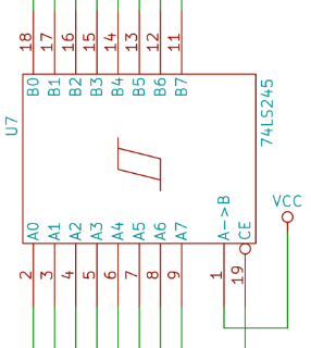
Pin Configuration and Descriptions
The 74LS245 is an 8-bit transceiver with 20 pins. Below is the pinout and description:
| Pin Number | Pin Name | Description |
|---|---|---|
| 1 | DIR | Direction control: Determines the direction of data flow (A ↔ B). |
| 2-9 | A1-A8 | Data bus A: 8-bit data input/output bus. |
| 10 | GND | Ground: Connect to system ground. |
| 11-18 | B1-B8 | Data bus B: 8-bit data input/output bus. |
| 19 | /OE | Output Enable (active low): Enables or disables the outputs. |
| 20 | Vcc | Power supply: Connect to +5V. |
Truth Table
The following table summarizes the operation of the 74LS245:
| /OE | DIR | Operation |
|---|---|---|
| Low | Low | Data flows from Bus B to Bus A |
| Low | High | Data flows from Bus A to Bus B |
| High | X | High-impedance state (disabled) |
Usage Instructions
How to Use the 74LS245 in a Circuit
- Power Supply: Connect the Vcc pin to a regulated +5V power supply and the GND pin to ground.
- Direction Control (DIR): Use the DIR pin to set the direction of data flow:
- Logic LOW (0): Data flows from Bus B to Bus A.
- Logic HIGH (1): Data flows from Bus A to Bus B.
- Output Enable (/OE): Use the /OE pin to enable or disable the outputs:
- Logic LOW (0): Enables the outputs for data transfer.
- Logic HIGH (1): Disables the outputs, placing them in a high-impedance state.
- Data Buses (A1-A8, B1-B8): Connect the data buses to the respective devices or systems. Ensure proper pull-up or pull-down resistors if required.
Important Considerations and Best Practices
- Avoid Bus Contention: Ensure that only one device drives the bus at a time to prevent damage or data corruption.
- Bypass Capacitors: Place a 0.1 µF ceramic capacitor close to the Vcc pin to filter noise and stabilize the power supply.
- Signal Integrity: Use short and properly routed traces to minimize noise and signal degradation.
- High-Impedance State: Use the high-impedance state to prevent interference when multiple devices share the same bus.
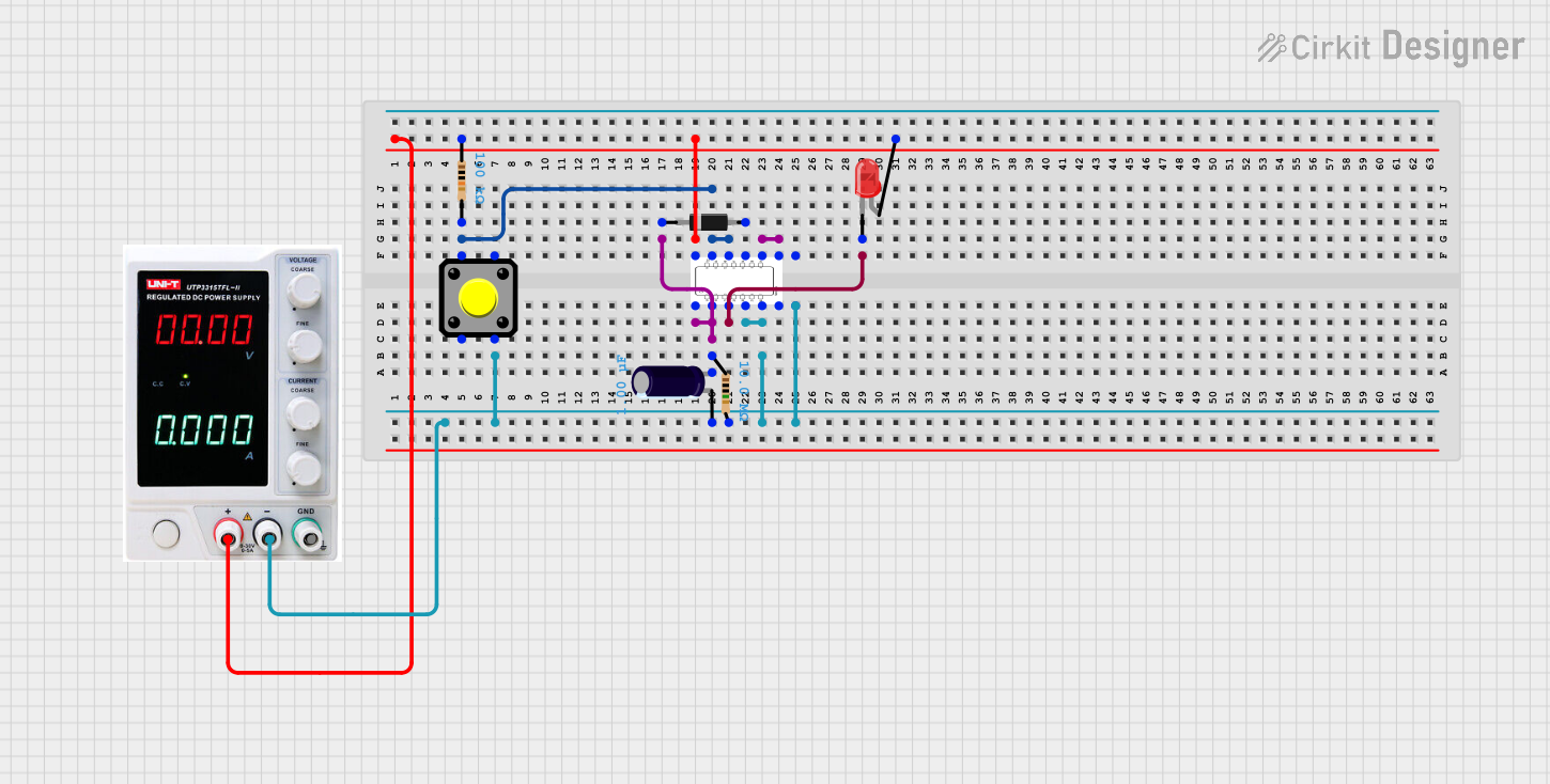
Example: Connecting the 74LS245 to an Arduino UNO
The following example demonstrates how to use the 74LS245 to interface an Arduino UNO with an 8-bit parallel device.
Circuit Connections
- Connect Vcc to the Arduino's 5V pin and GND to ground.
- Connect the DIR pin to Arduino digital pin 2.
- Connect the /OE pin to Arduino digital pin 3.
- Connect A1-A8 to the Arduino digital pins 4-11.
- Connect B1-B8 to the 8-bit parallel device.
Arduino Code
// Define pin connections
const int DIR_PIN = 2;  // Direction control pin
const int OE_PIN = 3;   // Output Enable pin

void setup() {
  // Set control pins as outputs
  pinMode(DIR_PIN, OUTPUT);
  pinMode(OE_PIN, OUTPUT);

  // Enable the outputs and set initial direction
  digitalWrite(OE_PIN, LOW);  // Enable outputs
  digitalWrite(DIR_PIN, HIGH); // Set direction: A to B
}

void loop() {
  // Example: Toggle direction every 2 seconds
  digitalWrite(DIR_PIN, HIGH); // Data flows from A to B
  delay(2000);                 // Wait for 2 seconds
  digitalWrite(DIR_PIN, LOW);  // Data flows from B to A
  delay(2000);                 // Wait for 2 seconds
}
Troubleshooting and FAQs
Common Issues and Solutions
No Data Transfer:
- Ensure the /OE pin is set to LOW to enable the outputs.
- Verify the DIR pin is correctly set for the desired data flow direction.
- Check all connections for continuity and proper wiring.
Bus Contention or Data Corruption:
- Ensure only one device drives the bus at a time.
- Use pull-up or pull-down resistors if required to stabilize the bus.
High Power Consumption:
- Check for short circuits or incorrect wiring.
- Ensure the device is not driving excessive loads beyond its rated current.
Signal Noise or Instability:
- Add bypass capacitors near the Vcc pin to filter noise.
- Use shorter traces and proper grounding techniques.
FAQs
Q1: Can the 74LS245 operate at 3.3V?
A1: No, the 74LS245 is designed for a supply voltage range of 4.75V to 5.25V. For 3.3V systems, consider using a level shifter or a compatible transceiver.
Q2: What is the maximum data rate supported by the 74LS245?
A2: The typical propagation delay is 12 ns, allowing for data rates up to approximately 83 MHz under ideal conditions.
Q3: Can I use the 74LS245 for unidirectional data transfer?
A3: Yes, you can fix the DIR pin to a specific logic level to enable unidirectional data transfer.
Q4: How do I connect multiple 74LS245 devices on the same bus?
A4: Use the /OE pin to enable only one device at a time, ensuring no two devices drive the bus simultaneously.