
How to Use buzzer: Examples, Pinouts, and Specs
 Design with buzzer in Cirkit Designer
Introduction
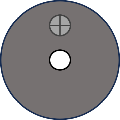
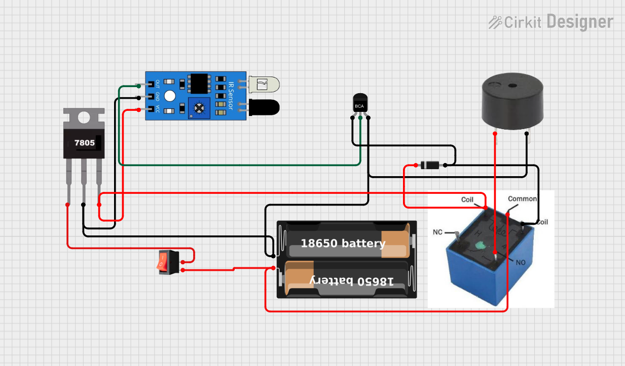
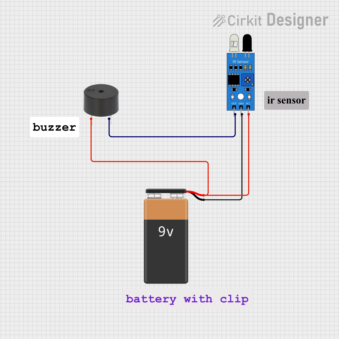
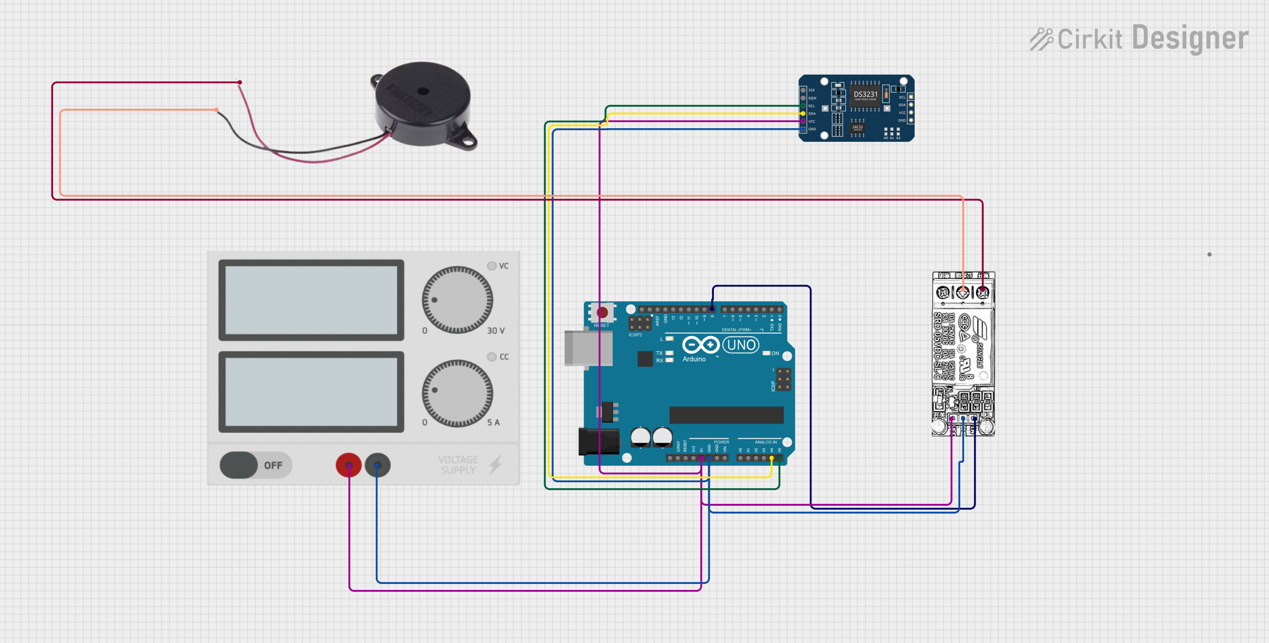
The JJY Buzzer (Part ID: bz) is an audio signaling device designed to produce sound when an electric current is applied. It is commonly used in a variety of applications, including alarms, timers, and notification systems. The buzzer is compact, reliable, and easy to integrate into electronic circuits, making it a popular choice for both hobbyists and professionals.
Explore Projects Built with buzzer
 Open Project in Cirkit Designer
 Open Project in Cirkit Designer
 Open Project in Cirkit Designer
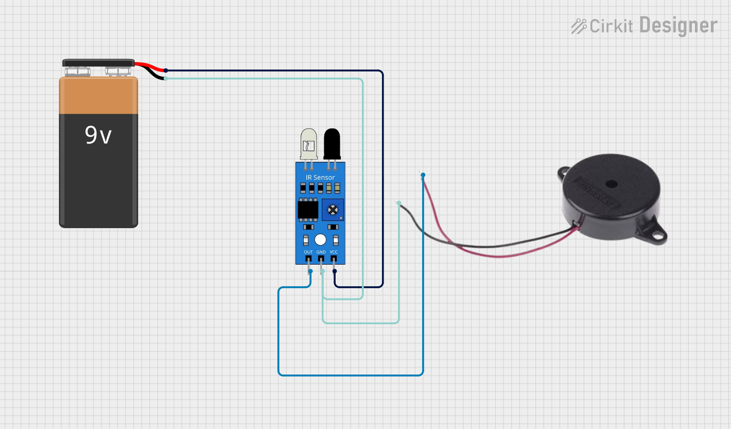 Open Project in Cirkit Designer
Explore Projects Built with buzzer
Open Project in Cirkit DesignerOpen Project in Cirkit DesignerOpen Project in Cirkit DesignerOpen Project in Cirkit DesignerCommon Applications
- Alarm systems (e.g., burglar alarms, fire alarms)
- Timers and reminders
- Notification systems in consumer electronics
- Feedback mechanisms in embedded systems
- Toys and educational projects
Technical Specifications
The following table outlines the key technical details of the JJY Buzzer (bz):
| Parameter | Value |
|---|---|
| Operating Voltage | 3V to 12V DC |
| Rated Voltage | 5V DC |
| Current Consumption | ≤ 30 mA |
| Sound Output Level | ≥ 85 dB at 10 cm |
| Frequency Range | 2 kHz to 4 kHz |
| Operating Temperature | -20°C to +60°C |
| Dimensions | 12 mm diameter, 8 mm height |
| Weight | 2 grams |
Pin Configuration
The JJY Buzzer has two pins for electrical connections:
| Pin | Description |
|---|---|
| Positive (+) | Connect to the positive terminal of the power supply or microcontroller output pin. |
| Negative (-) | Connect to the ground (GND) of the circuit. |
Usage Instructions
How to Use the Buzzer in a Circuit
- Power Supply: Ensure the buzzer is powered within its operating voltage range (3V to 12V DC). Exceeding this range may damage the component.
- Polarity: Connect the positive pin of the buzzer to the power source or microcontroller output pin, and the negative pin to the ground.
- Control: The buzzer can be controlled using a microcontroller (e.g., Arduino UNO) or a simple switch circuit. For microcontroller-based control, use a digital output pin to toggle the buzzer on or off.
Example Circuit with Arduino UNO
Below is an example of how to connect and control the JJY Buzzer using an Arduino UNO:
Circuit Diagram
- Connect the positive pin of the buzzer to Arduino digital pin 8.
- Connect the negative pin of the buzzer to the Arduino GND pin.
Arduino Code
// JJY Buzzer Example Code
// This code demonstrates how to control a buzzer using an Arduino UNO.
// The buzzer will beep on and off every 500 milliseconds.

#define BUZZER_PIN 8  // Define the pin connected to the buzzer

void setup() {
  pinMode(BUZZER_PIN, OUTPUT);  // Set the buzzer pin as an output
}

void loop() {
  digitalWrite(BUZZER_PIN, HIGH);  // Turn the buzzer on
  delay(500);                      // Wait for 500 milliseconds
  digitalWrite(BUZZER_PIN, LOW);   // Turn the buzzer off
  delay(500);                      // Wait for 500 milliseconds
}
Important Considerations
- Current Limiting: If the buzzer is powered directly from a microcontroller, ensure the current draw does not exceed the microcontroller's pin current rating (typically 20-40 mA for most microcontrollers).
- Noise Levels: The buzzer produces sound at ≥ 85 dB, which can be loud. Use caution when testing in close proximity to your ears.
- Mounting: Secure the buzzer in place to prevent vibrations from affecting other components in the circuit.
Troubleshooting and FAQs
Common Issues and Solutions
No Sound from the Buzzer
- Cause: Incorrect polarity or insufficient voltage.
- Solution: Verify the positive and negative connections. Ensure the power supply voltage is within the operating range (3V to 12V DC).
Buzzer Produces Weak or Distorted Sound
- Cause: Low supply voltage or insufficient current.
- Solution: Check the power supply and ensure it can provide adequate current (≥ 30 mA).
Buzzer Stays On Continuously
- Cause: Microcontroller output pin is stuck HIGH or there is a short circuit.
- Solution: Check the microcontroller code and wiring for errors.
Buzzer Does Not Respond to Microcontroller
- Cause: Incorrect pin configuration or damaged buzzer.
- Solution: Verify the microcontroller pin is set as an output and the buzzer is functional.
FAQs
Q: Can I use the JJY Buzzer with a 3.3V microcontroller?
A: Yes, the buzzer can operate at 3.3V, but the sound output may be slightly lower compared to 5V operation.
Q: Is the buzzer waterproof?
A: No, the JJY Buzzer is not waterproof. Avoid exposing it to moisture or liquids.
Q: Can I control the buzzer's volume?
A: The volume is fixed and cannot be adjusted. However, you can reduce the perceived loudness by adding a resistor in series with the buzzer.
Q: Can the buzzer produce different tones?
A: Yes, by using a microcontroller to generate a PWM signal, you can produce different tones within the buzzer's frequency range (2 kHz to 4 kHz).
This concludes the documentation for the JJY Buzzer (Part ID: bz). For further assistance, refer to the manufacturer's datasheet or contact technical support.