How to Use PX24506: Examples, Pinouts, and Specs

 Design with PX24506 in Cirkit Designer
Introduction
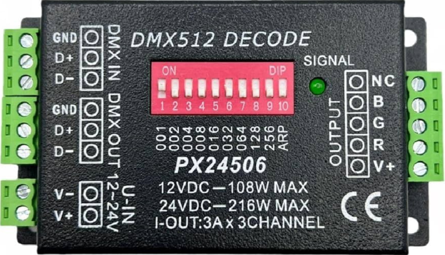
The PX24506 is a high-performance power management integrated circuit (PMIC) designed to provide efficient voltage regulation and power distribution in a wide range of electronic devices. With its multiple output channels, programmable settings, and robust protection mechanisms, the PX24506 ensures reliable operation in complex systems. It is ideal for applications such as embedded systems, IoT devices, portable electronics, and industrial automation.
Explore Projects Built with PX24506

 Open Project in Cirkit Designer
 Open Project in Cirkit Designer
 Open Project in Cirkit Designer
 Open Project in Cirkit Designer
Explore Projects Built with PX24506

 Open Project in Cirkit Designer
 Open Project in Cirkit Designer
 Open Project in Cirkit Designer
 Open Project in Cirkit Designer
Common Applications
- Embedded systems requiring multiple voltage rails
- IoT devices with strict power efficiency requirements
- Portable electronics such as smartphones and tablets
- Industrial automation systems with high reliability needs
Technical Specifications
Key Technical Details
| Parameter | Value |
|---|---|
| Input Voltage Range | 4.5V to 18V |
| Output Voltage Range | 0.8V to 5.5V (per channel) |
| Number of Output Channels | 4 |
| Maximum Output Current | 3A per channel |
| Efficiency | Up to 95% |
| Switching Frequency | 200 kHz to 2 MHz (programmable) |
| Protection Features | Overcurrent, Overvoltage, |
| Undervoltage, Thermal Shutdown | |
| Package Type | QFN-32 (5mm x 5mm) |
| Operating Temperature Range | -40°C to +125°C |
Pin Configuration and Descriptions
The PX24506 comes in a 32-pin QFN package. Below is the pin configuration and description:
| Pin Number | Pin Name | Description |
|---|---|---|
| 1 | VIN | Input voltage supply (4.5V to 18V) |
| 2-5 | VOUT1-4 | Output voltage channels 1 to 4 |
| 6 | EN | Enable pin for the IC |
| 7 | SYNC | Synchronization input for external clock |
| 8 | FB1-4 | Feedback pins for output voltage regulation |
| 9 | PG | Power Good indicator output |
| 10 | GND | Ground connection |
| 11-14 | NC | No connection (leave floating) |
| 15 | I2C_SCL | I2C clock for programmable settings |
| 16 | I2C_SDA | I2C data for programmable settings |
| 17-32 | Reserved | Reserved for future use (do not connect) |
Usage Instructions
How to Use the PX24506 in a Circuit
- Power Supply: Connect the VIN pin to a stable DC power source within the range of 4.5V to 18V. Ensure the power source can supply sufficient current for all output channels.
- Output Configuration: Use the FB1-4 pins to set the desired output voltage for each channel. This is typically done with a resistor divider network.
- Enable the IC: Pull the EN pin high to enable the PX24506. If left floating, the IC will remain disabled.
- Synchronization: If required, connect an external clock to the SYNC pin to synchronize the switching frequency.
- I2C Programming: Use the I2C_SCL and I2C_SDA pins to configure programmable settings such as output voltages, switching frequency, and protection thresholds.
- Power Good Monitoring: Monitor the PG pin to check the status of the output voltages. A high signal indicates all outputs are within the specified range.
Important Considerations and Best Practices
- Thermal Management: Ensure proper heat dissipation by using a PCB with adequate thermal vias and copper planes connected to the GND pin.
- Decoupling Capacitors: Place low-ESR decoupling capacitors close to the VIN and VOUT pins to minimize noise and improve stability.
- Startup Sequence: Configure the enable pin and I2C settings carefully to ensure a smooth startup sequence.
- Load Regulation: Verify the load regulation for each output channel to ensure stable operation under varying loads.
Example: Using PX24506 with Arduino UNO
The PX24506 can be controlled via I2C using an Arduino UNO. Below is an example code snippet to configure the output voltage of channel 1:
#include <Wire.h> // Include the Wire library for I2C communication

#define PX24506_I2C_ADDRESS 0x40 // Replace with the actual I2C address of PX24506

void setup() {
  Wire.begin(); // Initialize I2C communication
  Serial.begin(9600); // Initialize serial communication for debugging

  // Configure output voltage for channel 1 to 3.3V
  Wire.beginTransmission(PX24506_I2C_ADDRESS);
  Wire.write(0x01); // Register address for channel 1 voltage setting
  Wire.write(0x33); // Data to set output voltage to 3.3V
  Wire.endTransmission();

  Serial.println("PX24506 configured for 3.3V on channel 1");
}

void loop() {
  // Add your main code here
}
Troubleshooting and FAQs
Common Issues and Solutions
No Output Voltage
- Cause: The EN pin is not pulled high.
- Solution: Ensure the EN pin is connected to a high logic level to enable the IC.
Output Voltage is Incorrect
- Cause: Incorrect resistor divider network on the FB pins or incorrect I2C configuration.
- Solution: Verify the resistor values and recheck the I2C settings.
Overheating
- Cause: Insufficient thermal management or excessive load current.
- Solution: Improve PCB thermal design and ensure the load current does not exceed 3A per channel.
I2C Communication Fails
- Cause: Incorrect I2C address or wiring issues.
- Solution: Verify the I2C address and check the connections to the SCL and SDA pins.
FAQs
Q: Can the PX24506 operate without I2C programming?
A: Yes, the PX24506 can operate with default settings if the I2C pins are left unconnected.Q: What happens if the input voltage drops below 4.5V?
A: The IC will enter undervoltage protection mode and disable the outputs to prevent damage.Q: Can I use all four output channels simultaneously?
A: Yes, all four channels can be used simultaneously, provided the total current does not exceed the input power supply's capacity.
This concludes the documentation for the PX24506. For further assistance, refer to the manufacturer's datasheet or contact technical support.