How to Use IronHorse IEC contactor: Examples, Pinouts, and Specs
Introduction
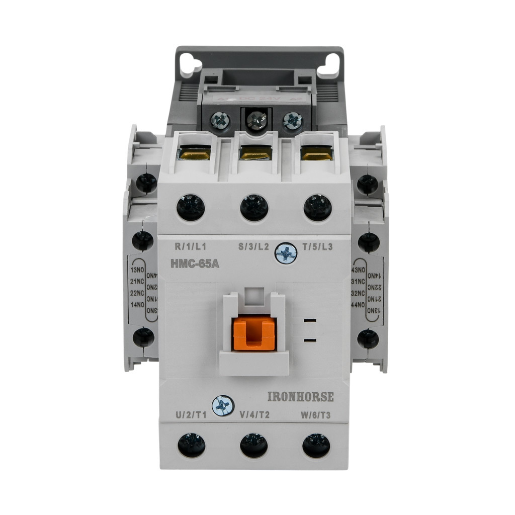
The IronHorse IEC Contactor (HMC-65A30-22-DL) is a robust electrical device designed to control the flow of electricity in a circuit. It is primarily used for switching motors and other heavy electrical loads. Manufactured to meet international standards, this contactor is known for its reliability, efficiency, and durability, making it an essential component in industrial and commercial applications.
Explore Projects Built with IronHorse IEC contactor


Explore Projects Built with IronHorse IEC contactor
Common Applications and Use Cases
- Motor control in industrial machinery
- Switching heavy electrical loads
- HVAC systems
- Lighting control in commercial buildings
- Automation systems
Technical Specifications
The following table outlines the key technical details of the IronHorse IEC Contactor:
| Parameter | Specification |
|---|---|
| Manufacturer | IronHorse |
| Part Number | HMC-65A30-22-DL |
| Rated Operational Voltage | 690V AC |
| Rated Current | 65A |
| Coil Voltage | 24V DC |
| Frequency | 50/60 Hz |
| Number of Poles | 3 (Three-phase) |
| Auxiliary Contacts | 2 NO (Normally Open), 2 NC (Normally Closed) |
| Mechanical Durability | 10 million operations |
| Electrical Durability | 1 million operations |
| Operating Temperature Range | -25°C to +60°C |
| Mounting Type | DIN rail or panel mount |
| Standards Compliance | IEC 60947-4-1, CE, UL certified |
Pin Configuration and Descriptions
The IronHorse IEC Contactor features the following terminal layout:
| Pin/Terminal | Description |
|---|---|
| L1, L2, L3 | Main power input terminals for three-phase supply |
| T1, T2, T3 | Main power output terminals to the load |
| A1, A2 | Coil terminals for control voltage (24V DC) |
| 13, 14 | Auxiliary contact (Normally Open - NO) |
| 21, 22 | Auxiliary contact (Normally Closed - NC) |
Usage Instructions
How to Use the Component in a Circuit
Power Connections:
- Connect the three-phase power supply to the input terminals (L1, L2, L3).
- Connect the load (e.g., motor) to the output terminals (T1, T2, T3).
Control Circuit:
- Supply 24V DC to the coil terminals (A1 and A2) to energize the contactor.
- Use auxiliary contacts (13-14 for NO, 21-22 for NC) for additional control or feedback in the circuit.
Mounting:
- Secure the contactor to a DIN rail or panel mount as per your application requirements.
Safety Precautions:
- Ensure the power supply is disconnected before installation or maintenance.
- Verify that the contactor's ratings match the load requirements to prevent damage.
Important Considerations and Best Practices
- Overload Protection: Use an appropriate overload relay in conjunction with the contactor to protect the load.
- Wiring: Use wires of the correct gauge to handle the rated current.
- Environment: Avoid installing the contactor in environments with excessive dust, moisture, or vibration.
- Testing: After installation, test the contactor operation by energizing the coil and verifying the switching of the load.
Example: Connecting to an Arduino UNO
The IronHorse IEC Contactor can be controlled using an Arduino UNO by interfacing the coil terminals (A1 and A2) with a relay module. Below is an example code snippet:
// Example: Controlling the IronHorse IEC Contactor with Arduino UNO
// This code energizes the contactor coil for 5 seconds, then de-energizes it.

const int relayPin = 7; // Pin connected to the relay module

void setup() {
  pinMode(relayPin, OUTPUT); // Set relayPin as an output
  digitalWrite(relayPin, LOW); // Ensure the relay is off initially
}

void loop() {
  digitalWrite(relayPin, HIGH); // Energize the relay (and the contactor coil)
  delay(5000); // Keep the contactor energized for 5 seconds
  digitalWrite(relayPin, LOW); // De-energize the relay (and the contactor coil)
  delay(5000); // Wait for 5 seconds before repeating
}
Note: Use a relay module to interface the Arduino with the contactor coil, as the Arduino cannot directly supply the required current for the coil.
Troubleshooting and FAQs
Common Issues and Solutions
Contactor Does Not Energize:
- Cause: No control voltage at the coil terminals (A1, A2).
- Solution: Check the control circuit and ensure 24V DC is supplied to the coil.
Excessive Heating:
- Cause: Overloaded contactor or poor ventilation.
- Solution: Verify the load does not exceed the rated current (65A). Ensure proper ventilation around the contactor.
Chattering Noise:
- Cause: Insufficient or unstable control voltage.
- Solution: Check the power supply to the coil and ensure it is stable and within the rated voltage.
Auxiliary Contacts Not Working:
- Cause: Incorrect wiring or damaged contacts.
- Solution: Verify the wiring of the auxiliary contacts and check for continuity.
FAQs
Q1: Can this contactor be used with single-phase loads?
A1: Yes, the contactor can be used with single-phase loads by connecting only one pair of input and output terminals (e.g., L1 and T1).
Q2: What is the purpose of the auxiliary contacts?
A2: Auxiliary contacts are used for control or feedback purposes, such as signaling the status of the contactor to a control system.
Q3: How do I select the correct overload relay for this contactor?
A3: Choose an overload relay with a current rating that matches the load's full-load current and is compatible with the contactor.
Q4: Can the contactor operate in extreme temperatures?
A4: The contactor is designed to operate within a temperature range of -25°C to +60°C. For extreme conditions, additional measures like enclosures or heaters may be required.